Method to measure aircraft high-lift system brake response time

a technology for high-lift systems and response time, which is applied in the direction of braking systems, braking components, transportation and packaging, etc., can solve the problems of increasing the response time of the engagement of the brake, and affecting the safety of the aircra

Active Publication Date: 2018-11-08
HAMILTON SUNDSTRAND CORP
View PDF3 Cites 12 Cited by
  • Summary
  • Abstract
  • Description
  • Claims
  • Application Information

AI Technical Summary

Benefits of technology

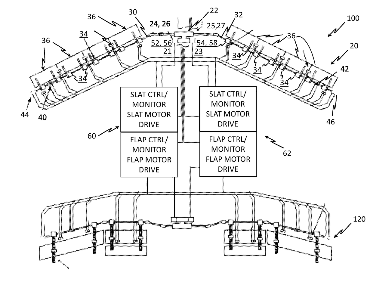
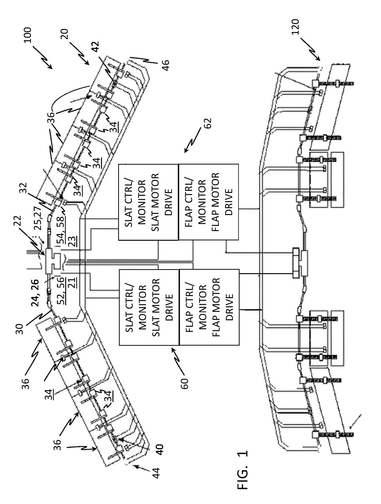
[0038]Each of the transmission shafts 30, 32 also includes a wing tip brake 40, 42 in a region around the outer end of each of the shafts 30, 32, which may be at an outer end of the respective wing. Typically, the location of the wingtip brake 40, 42, is at the end of the driveline. However, some applications may require the wingtip brake 40, 42 to be installed inboard of the most outboard actuator due to re...

Problems solved by technology

Moreover, brake systems can develop degraded performance over life due to electrical variations, mechanical wear and environmental exposure all of which will increase the b...

Method used


Image

  • Method to measure aircraft high-lift system brake response time
  • Method to measure aircraft high-lift system brake response time
  • Method to measure aircraft high-lift system brake response time

Examples


Embodiment Construction

[0032]For the purposes of promoting an understanding of the principles of the present disclosure, reference will now be made to the embodiments illustrated in the drawings, and specific language will be used to describe the same. It will nevertheless be understood that no limitation of the scope of this disclosure is thereby intended. The following description is merely illustrative in nature and is not intended to limit the present disclosure, its application or uses. It should be understood that throughout the drawings, corresponding reference numerals indicate like or corresponding parts and features. As used herein, the term controller refers to processing circuitry that may include an application specific integrated circuit (ASIC), an electronic circuit, an electronic processor (shared, dedicated, or group) and memory that executes one or more software or firmware programs, a combinational logic circuit, and / or other suitable interfaces and components that provide the described...


PUM


Abstract

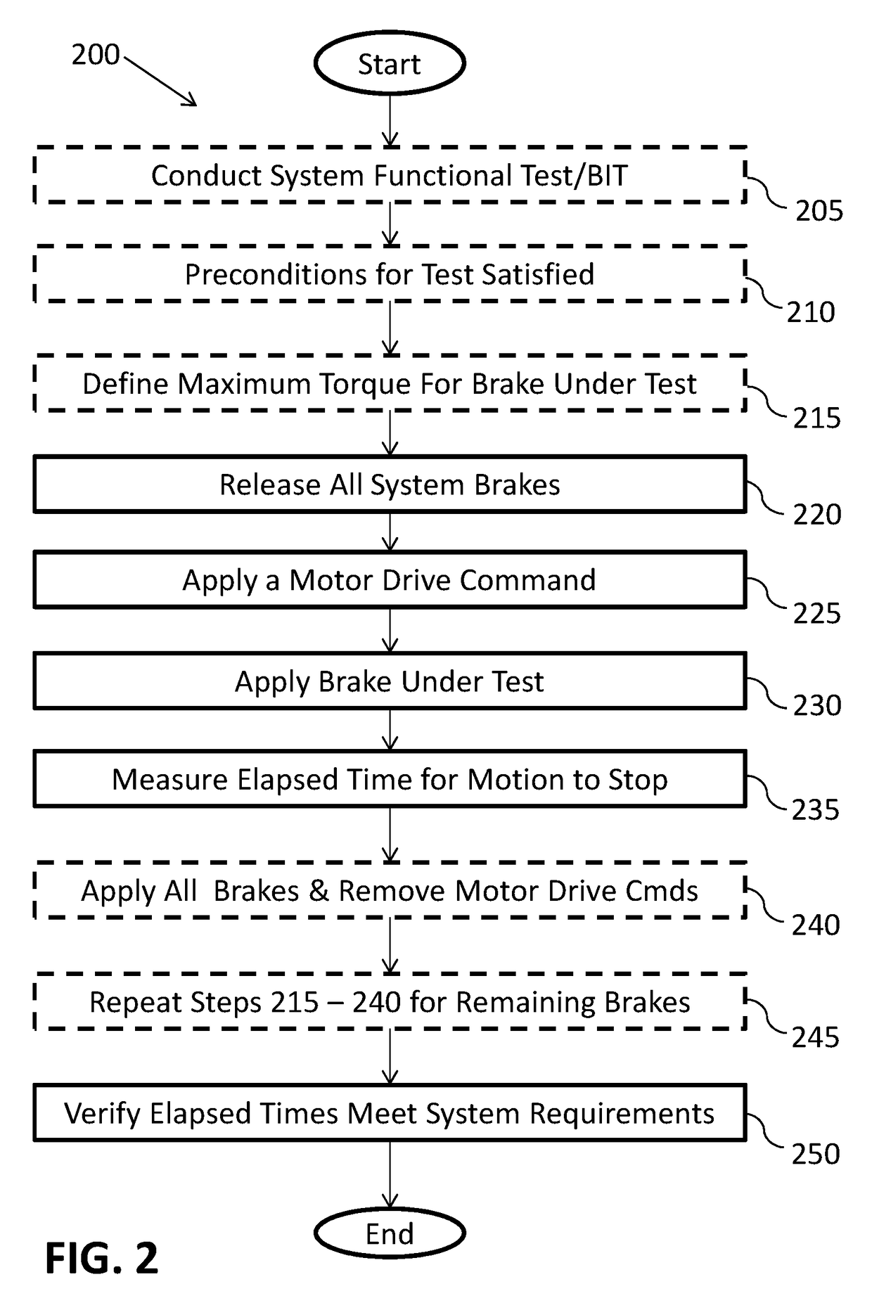
A braking test for a high lift system. The system including a plurality of high lift surfaces movably arranged at a wing, a plurality of drive stations coupled with the high lift surfaces via a transmission shaft, a power drive unit coupled with the transmission shaft including an electric motor operably coupled with a brake, and a control unit operably coupled to the power drive unit. The control unit executing a method for testing the brake, including actuating an electric motor, acquiring a sensor output of a sensor coupled during the actuating of the motor and determining a motion of the motor, activating a selected brake under test, measuring an elapsed time until the brake has arrested the motion, and determining if the elapsed time is less than a threshold. Generating a brake failure signal for the selected brake if the elapsed time exceeds the threshold.

Description

TECHNICAL FIELD[0001]This disclosure relates to a method for testing a component in a high lift system of an aircraft, a high lift system of an aircraft as well as an aircraft having at least one such high lift system. The disclosure can also be applicable to other systems including, but not limited to, horizontal stabilizers, utility actuators, and the like, which rely on a brake response time as a critical function of its operating performanceBACKGROUND[0002]Typically, high lift systems of commercial and military aircraft are powered by a centralized drive, also known as a power drive unit (PDU). Such drives are mounted in a central region of the fuselage: and are controllable through a computerized control system or electronics unit. The PDU is coupled with a torque shaft system, also known as transmission shaft, which transfers mechanical power to geared actuators at flap or slat panel drive stations distributed along the trailing edge or leading; edge of a wing. The control of ...

Claims


Application Information

Patent Timeline
IPC IPC(8): B64C13/50B60T8/17B60T17/22B64C9/24B64C9/18B64D45/00H02P29/04H02P29/024H02K7/102H02K11/21H02K11/24H02K7/14
CPCB64C13/50B60T8/1703B60T17/221B64C9/24B64C9/18B64D45/00B64D2045/0085H02P29/024H02K7/102H02K11/21H02K11/24H02K7/14B60T2270/406H02P29/04B60T8/173B60T8/885B64C13/503B64F5/60H02P29/0241
Inventor MAYER, TIMOTHY MICHAELPEREZ, ARTEMIOBARGER, VICTOR
Owner HAMILTON SUNDSTRAND CORP
Why Eureka
Try Eureka