
Method of noise filtering a sliding camshaft actuator pin position output signal

Active Publication Date: 2018-11-08
GM GLOBAL TECH OPERATIONS LLC
View PDF0 Cites 0 Cited by
  • Summary
  • Abstract
  • Description
  • Claims
  • Application Information

AI Technical Summary

Benefits of technology

The patent aims to improve the accuracy of measuring output signals by adjusting the predetermined output signal period based on temperature and rejecting signals that occur outside of the pin position output signal filter window, which can help reduce false diagnostic codes.

Problems solved by technology

It is appreciated that output signals from sensing devices are susceptible to electrical noise generated by the outside environment or other components during vehicle operation.
Such electrical noise could be read and falsely perceived by the engine controller as a pin position state change which, in turn, could lead to a diagnostic fault code being set and remedial action being inadvertently performed.

Method used


Image

  • Method of noise filtering a sliding camshaft actuator pin position output signal
  • Method of noise filtering a sliding camshaft actuator pin position output signal
  • Method of noise filtering a sliding camshaft actuator pin position output signal

Examples


Embodiment Construction

[0014]The following detailed description is merely exemplary in nature and is not intended to limit the embodiment or the application and uses thereof. Furthermore, there is no intention to be bound by any theory presented in the preceding background or the following detailed description.

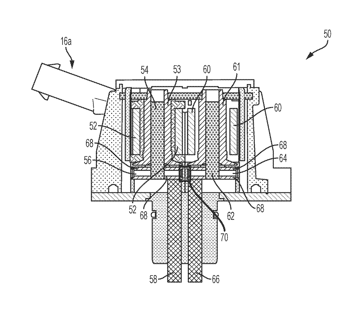
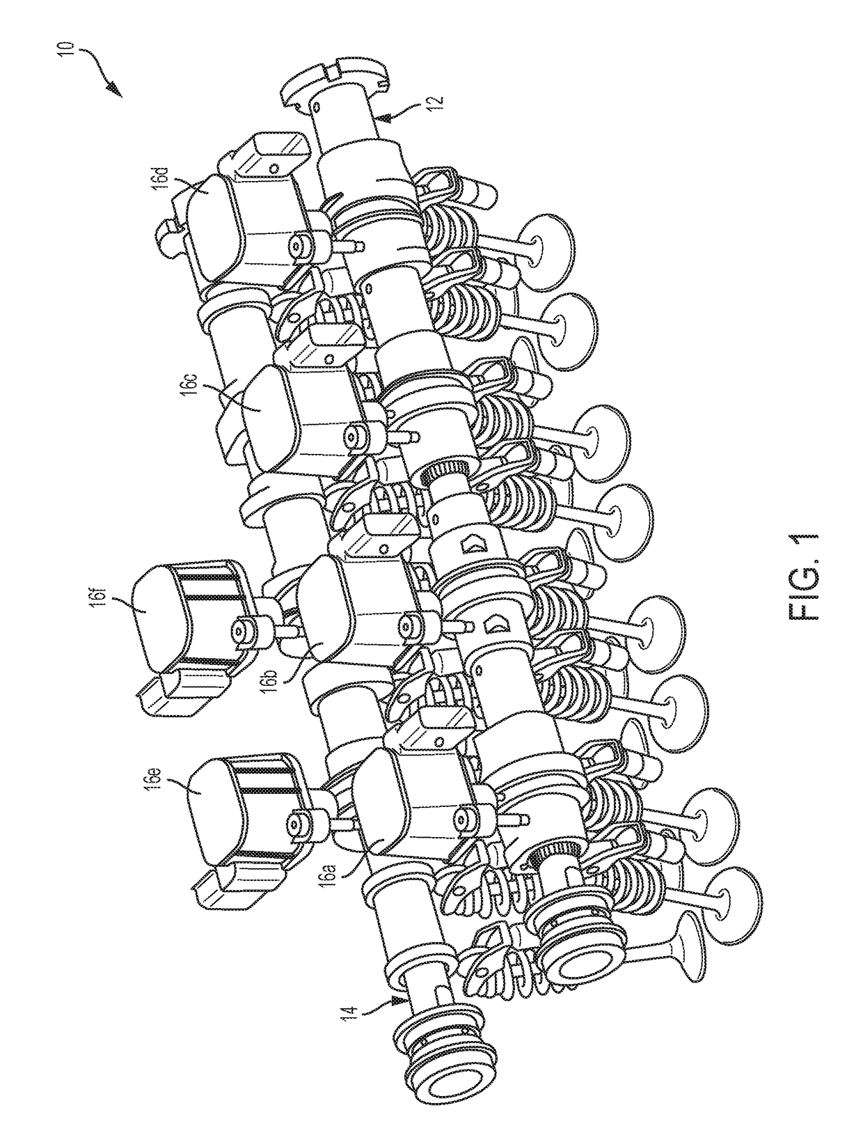
[0015]In accordance with the disclosed embodiment, FIG. 1 is an illustration of an intake and an exhaust sliding camshaft configuration for a 4 cylinder internal combustion engine camshaft system 10 in accordance with aspects of an exemplary embodiment. It is appreciated that the 4 cylinder embodiment is merely exemplary and the concept of sliding camshaft barrel position sensing may be applied to other multiple cylinder engine camshaft system configurations, e.g., 5, 6, 8, 9, or 12, without exceeding the scope of the invention.

[0016]The camshaft system 10 includes at least one sliding camshaft having at least one camshaft barrel. In the case, the camshaft system 10 includes a three (3) step intake ...


PUM


Abstract

A method of noise filtering a sliding camshaft actuator pin position output signal includes determining an actual pin position output signal period of a sliding camshaft actuator that occurs within a predetermined output signal period measurement window and establishing a pin position output signal filter window based on the actual pin position output signal period. Thereafter, the actual pin position output signal period from the sliding camshaft actuator is monitored by a control module and signals that occur outside of the pin position output signal filter window are rejected accordingly to prevent responding to false triggers.

Description

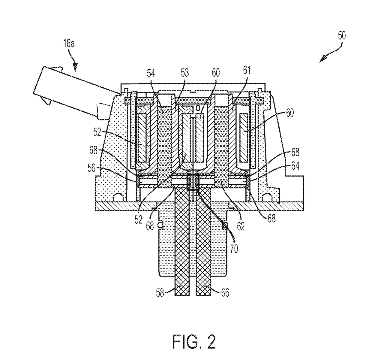
TECHNICAL FIELD[0001]The present invention generally relates to sliding camshaft actuators for variable valve lift (VVL) systems and, more particularly, relates to a method of noise filtering a sliding camshaft actuator pin position output signal.BACKGROUND[0002]Internal combustion engines include intake and exhaust valves that can be actuated by cam lobes of at least one camshaft. In some configurations the camshafts are constructed with sliding camshaft assemblies having multiple steps for varying the lift distance of an engine valve. For example, a two-step sliding camshaft may include a high lift cam lobe position for lifting an engine valve to a maximum distance, and a low lift cam lobe position for lifting the engine valve below the maximum lift distance.[0003]At least one sliding camshaft actuator is fixed on an internal combustion engine for changing position between the multiple cam lobes. Particularly, at least one actuator pin of a camshaft actuator is operative to select...

Claims


Application Information

Patent Timeline
IPC IPC(8): F01L13/00G01D5/14
CPCF01L13/0036G01D5/142F01L2820/041F01L2013/0052F01L2013/111G01B7/003F01L2800/14G01D3/032F01L1/053F01L1/185F01L2001/0537F01L2013/101F01L2305/00
Inventor VERNER, DOUGLAS R.KARNJATE, TIMOTHYPHILIPPART, TIMOTHY P.
Owner GM GLOBAL TECH OPERATIONS LLC
Learn More