Road surface detection system

a detection system and road surface technology, applied in the direction of vehicle position/course/altitude control, process and machine control, instruments, etc., can solve the problems of reducing the vehicle may get out of control, so as to reduce the friction coefficient of the road surface

Inactive Publication Date: 2018-11-08
MAGNA ELECTRONICS
View PDF5 Cites 19 Cited by
  • Summary
  • Abstract
  • Description
  • Claims
  • Application Information

AI Technical Summary

Benefits of technology

[0004]The present invention provides a road detection system that utilizes reflectance spectroscopy to determine the road surface composition in front of a moving vehicle to detect substances like water, ice, oil, snow, dirt or sand that reduce the road surface friction and present a hazard. The road surface detection system includes a broad band optical emitter disposed at the vehicle and configured to emit a beam of light downward and forward of the vehicle, and a receiver disposed at the vehicle so as to receive light emitted by the broad band optical emitter that is scattered or reflect

Problems solved by technology

Motor vehicles may encounter substances on the road that reduce the road surface friction coefficient (e.g. oil spills or sand or gravel).
When the v

Method used


Image

  • Road surface detection system
  • Road surface detection system
  • Road surface detection system

Examples


Embodiment Construction

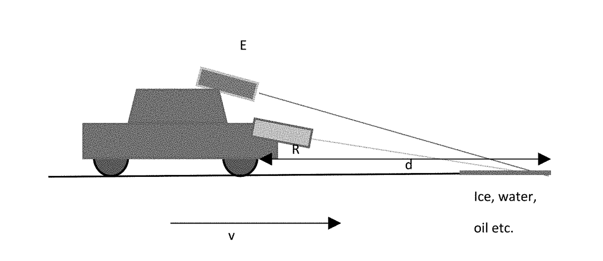
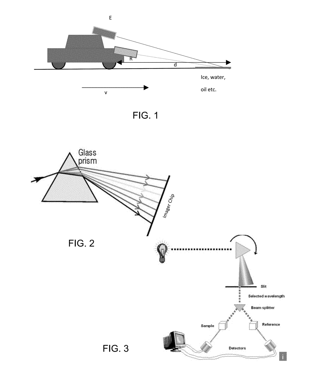
[0012]Referring now to the drawings and the illustrative embodiments depicted therein, a road surface detector of a vehicle includes a broad band optical emitter E and a receiver R (FIG. 1). The broad band optical emitter E emits a beam of light that hits the road surface. A part of the light is scattered or reflected from the road surface and is received by the receiver R.

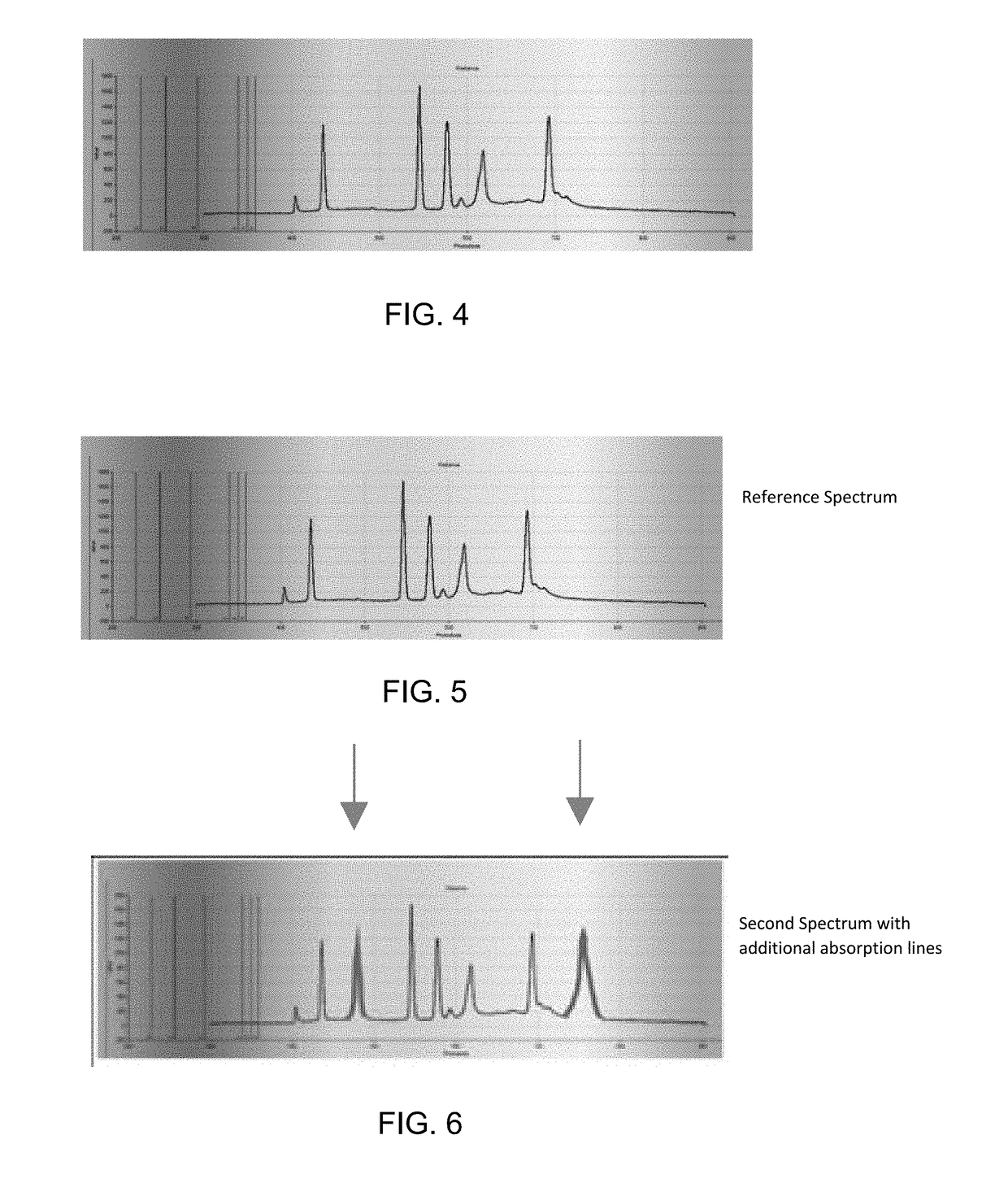
[0013]In the receiver R, a prism (see FIG. 2) refracts the light and the imager chip captures the intensity of the spectrum. The system may scan a wide spectrum using a rotating prism and a slit (such as shown in FIG. 3). Different materials present on the road surface absorb parts of the spectrum and generate an absorption ‘fingerprint’ of the material present on the road surface.

[0014]A machine learning algorithm (deep neural network) is utilized to analyze the recorded spectra to determine the presence of one or multiple substance quickly and securely.

[0015]The receiver R then compares the spectrum received aga...


PUM


Abstract

A road surface detection system for a vehicle includes an optical emitter disposed at the vehicle and configured to emit a beam of light downward and forward of the vehicle. A receiver is disposed at the vehicle so as to receive light emitted by the optical emitter that is scattered or reflected from the road surface. The receiver includes a prism and an imager, and the prism refracts the light so that the imager captures received light that is refracted by the prism. A control includes a processor operable to process image data captured by the imager. The control, responsive to processing of image data captured by the imager, determines spectral characteristics of materials present on the road surface. The control may determine the type of material present on the road surface by determining the parts of the spectrum absorbed by the material.

Description

CROSS REFERENCE TO RELATED APPLICATION[0001]The present application is related to U.S. provisional application Ser. No. 62 / 501,987, filed May 5, 2017, which is hereby incorporated herein by reference in its entirety.FIELD OF THE INVENTION[0002]The present invention relates generally to a vehicle sensing system for a vehicle and, more particularly, to a vehicle sensing system that utilizes one or more cameras at a vehicle.BACKGROUND OF THE INVENTION[0003]Motor vehicles may encounter substances on the road that reduce the road surface friction coefficient (e.g. oil spills or sand or gravel). When the vehicle travels on these coated surfaces the vehicle may get out of control when attempting to navigate a curve or when deceleration or accelerating. This is especially important for autonomous vehicles that cannot rely on a human driver to detect these hazards; these vehicles need to detect the hazards in time and then react proactively by, for example, avoiding the hazard or deceleratio...

Claims


Application Information

Patent Timeline
IPC IPC(8): G01N21/3554
CPCG01N21/3554G05D1/0231B60Q9/00G05D2201/0213G01N21/49G01N21/31G01N2021/4709G01N2021/4735G01N2201/0216B60W40/06B60W50/14B60W2420/403B60W30/00
Inventor SEIFERT, HEINZ B.
Owner MAGNA ELECTRONICS
Why Eureka
Try Eureka