Apparatus for laser hardfacing using a wobbling movement

a laser hardfacing and wobbling technology, applied in the direction of additive manufacturing processes, soldering apparatus, manufacturing tools, etc., can solve the problem of laser radiation wobbling and achieve the effect of high quality

Inactive Publication Date: 2018-11-15
FRAUNHOFER GESELLSCHAFT ZUR FOERDERUNG DER ANGEWANDTEN FORSCHUNG EV +1
View PDF0 Cites 1 Cited by
  • Summary
  • Abstract
  • Description
  • Claims
  • Application Information

AI Technical Summary

Benefits of technology

[0021]A turbine blade is preferably used as the workpiece. The method is particularly suitable for workpieces having large dimensions, because the latter can be repaired in a material-saving manner and with high quality by the method.

Problems solved by technology

However, conventional systems for hardfacing are not conceived such that the laser radiation can be wobbled.

Method used


Image

  • Apparatus for laser hardfacing using a wobbling movement
  • Apparatus for laser hardfacing using a wobbling movement
  • Apparatus for laser hardfacing using a wobbling movement

Examples


Embodiment Construction

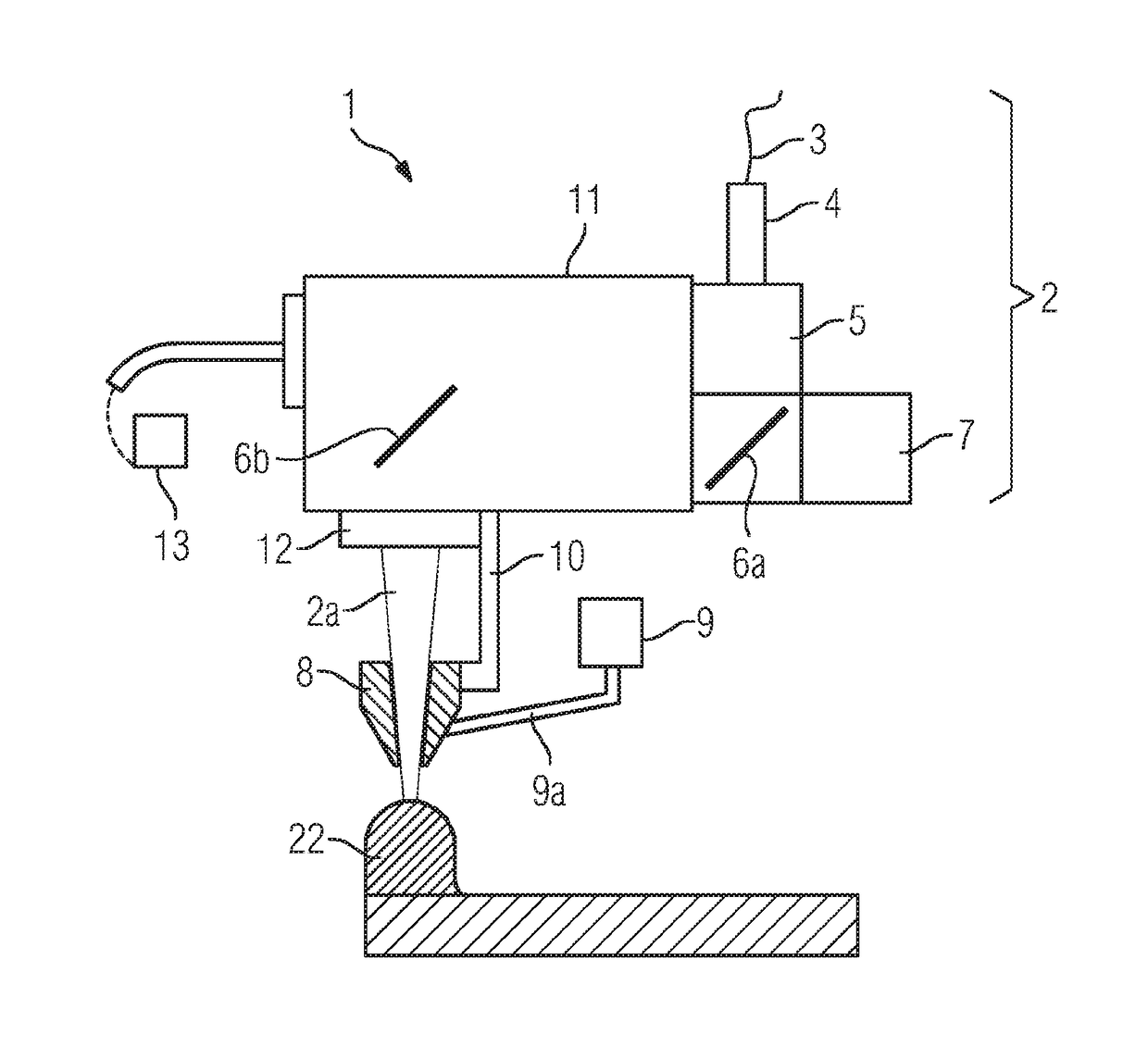
[0031]A device 1 according to embodiments of the invention in an embodiment according to the illustration of FIG. 1 comprises a laser installation 2 having a fiber cable 3, a fiber plug 4, and an installation for collimating 5. The fiber cable 3 is preferably a glass fiber cable, but can also comprise another material, for example polymers. The fiber plug 4 serves for releasably connecting the fiber cable 3 to further components such as the installation for collimating 5, also referred to as the collimator 5. The laser installation 2 furthermore has a deflection mirror having a dichroic mirror 6a so as to direct the path of a laser beam 2a. A CCD camera 7 is fitted in the region of the deflection mirror 6a. Visible light is transmitted through the dichroic mirror 6a.

[0032]The light conducting fiber 3 is connected to a laser beam source (not shown). The laser radiation is generated in this laser beam source and guided by the fiber 3 into a scanner unit 11. The laser beam 2a is guide...


PUM

PropertyMeasurementUnit
high-temperature-resistantaaaaaaaaaa
microstructureaaaaaaaaaa
material propertiesaaaaaaaaaa

Abstract

A device for laser hardfacing is provided, in which a scanner installation and a feed installation for a material provided for hardfacing are disposed so as to be interconnected. The device furthermore includes a laser installation and a control installation. Wobbling of the laser beam during the laser hardfacing can be carried out by the device. A method for laser hardfacing using a wobbling movement is furthermore provided.

Description

CROSS-REFERENCE TO RELATED APPLICATIONS[0001]This application claims priority to PCT Application No. PCT / EP2016 / 074287, having a filing date of Oct. 11, 2016, based on German Application No. 10 2015 222 083.4, having a filing date of Nov. 10, 2015, the entire contents both of which are hereby incorporated by reference.FIELD OF TECHNOLOGY[0002]The following relates to a device for laser hardfacing using a wobbling movement of a laser beam, in which a scanner and a feed device are disposed in an interconnected manner.BACKGROUND[0003]Laser hardfacing is associated with methods of hardfacing in which a surface buildup on a workpiece is performed by means of applying and simultaneously fusing an additional material. The material is often fed in a pulverulent form, for example as a metal powder, or in the form of a wire, is fused, and the fused material is applied. A laser which is suitable for locally heating and fusing the material of the workpiece serves as an energy source. The additi...

Claims


Application Information

Patent Timeline
Patent Type & Authority Applications(United States)
IPC IPC(8): B23K26/082B23K26/342B23K26/144B29C64/153
CPCB23K26/082B23K26/342B23K26/144B29C64/153B22F2003/1056B22F2999/00B23K35/3033B23K35/0244B33Y10/00B33Y30/00B23K2101/001Y02P10/25B22F12/49B22F10/38B22F12/44B22F10/28B22F12/53B22F10/50B22F10/36B22F5/04B22F2007/068B22F2203/03B22F2202/11
Inventor MENTZEL, FRANKBOSTANJOGLO, GEORGBURBAUM, BERNDGASSER, ANDRESLINNENBRINK, STEFANIEPIRCH, NORBERTWEYLAND, MICHAEL
Owner FRAUNHOFER GESELLSCHAFT ZUR FOERDERUNG DER ANGEWANDTEN FORSCHUNG EV
Why Eureka
Try Eureka