Ink formulation

a technology of formulation and pigment, applied in the field of pigment formulation, can solve the problems of high boiling point, toxic, high cost, etc., and cannot be applied to the production of heterostructures on a large scale,

Active Publication Date: 2018-11-15
UNIV OF MANCHESTER
View PDF1 Cites 4 Cited by
  • Summary
  • Abstract
  • Description
  • Claims
  • Application Information

AI Technical Summary

Benefits of technology

[0017]wherein the nanosheets are associated with a stabiliser that renders the nanosheets dispersible within the aqueous vehicle and the aqueous vehicle further comprises at least one surface tension modifier and at least one viscosity modifier;

Problems solved by technology

While this technique enables the production of extremely high quality heterostructures, it cannot be applied to the production of such heterostructures on a large scale.
Currently this is mostly based on the use of organic solvents such as N-Methylpyrrolidone (NMP) and N,N-dimethylformamide (DMF), which are toxic, expensive and characterized by high boiling points.
However, the presence of excess stabiliser can be undesirable as it may affect the mechanical and electrical properties of the printed ink.

Method used


Image

  • Ink formulation
  • Ink formulation
  • Ink formulation

Examples


example 1

Dispersions

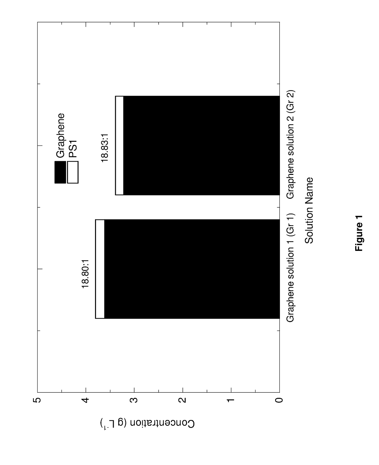
[0259]The following quantities of reagents were added to a 12 mL glass vial:[0260]H2O—9.0 g;[0261]Propylene glycol—1.0 g;[0262]Triton-x100—0.6 mg;[0263]Graphite (flakes>100 μm)—30 mg; and[0264]1-pyrenesulfonic acid sodium salt (PS1)—10 mg.

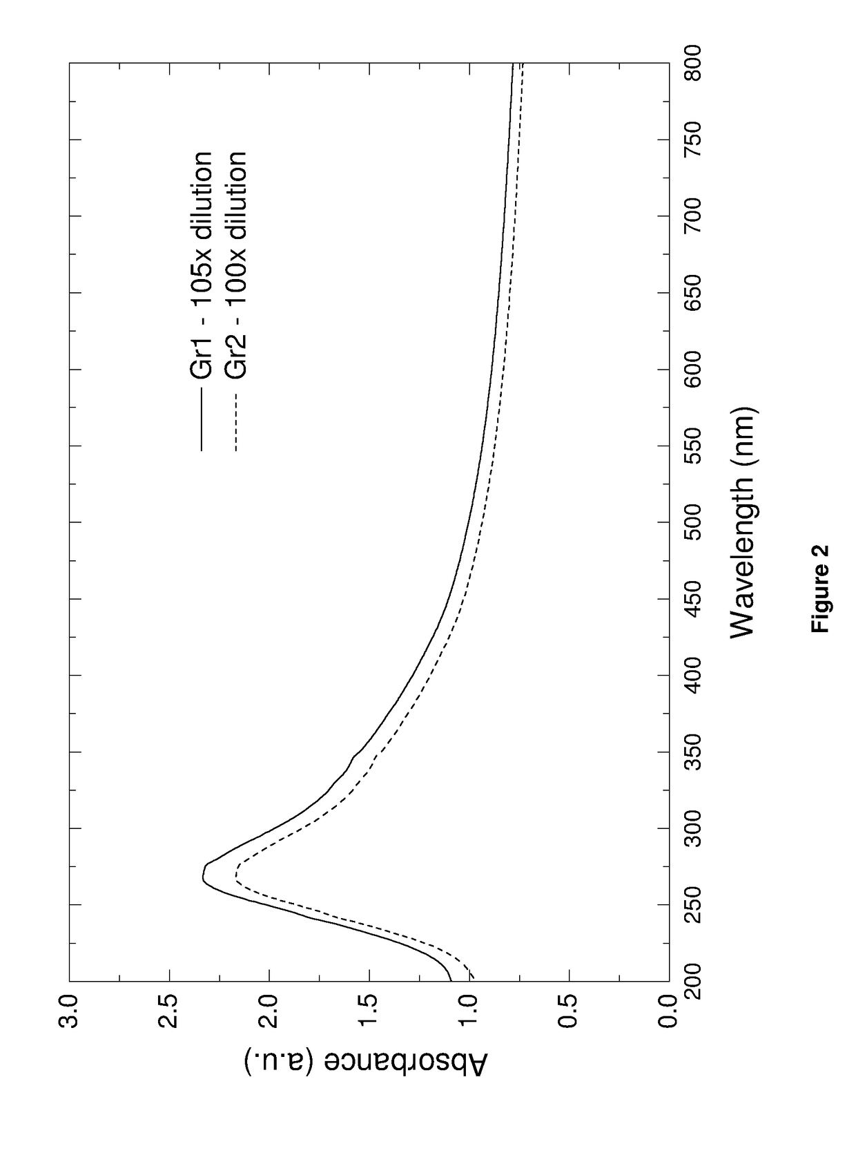
[0265]The inkjet formulation was prepared using the quantities of reagents detailed above, by means of the following steps:[0266]1) The glass vial was stoppered and placed into a 600 W bath sonicator for 48 hours.[0267]2) The solution was then centrifuged at 3500 rpm (903 g) for 20 mins and the top ⅔ collected.[0268]3) The collected solution was then centrifuged at 15000 rpm (16602 g) for 20 mins and the supernatant collected and combined before UV-Vis was conducted using a Cary 5000 UV-Vis-Near IR spectrometer to determine the concentration of PS1 in the supernatant.[0269]4) The sediment was gently re-dispersed via shaking in a solvent comprising of H2O (90% by weight), propylene glycol (10% by weight) and Triton-x100 (6×10⁻³% by weight...

example 2

ersions

[0301]The following quantities of reagents were added to a glass vial:[0302]H2O—9.0 g;[0303]Propylene glycol—1.0 g;[0304]Triton-x100—0.6 mg;[0305]h-BN powder (˜1 μm)—30 mg[0306]1-pyrenesulfonic acid sodium salt—10 mg.

[0307]The inkjet formulation was prepared using the quantities of reagents detailed above, by means of the following steps:

1) The glass vial was then stoppered and placed into a 600 W bath sonicator for 48 hours.

2) The solution was then centrifuged at 3500 rpm (903 g) for 20 mins and the top ⅔ collected.

3) The collected solution was then centrifuged at 15000 rpm (16602 g) for 20 mins and the supernatant collected and combined before UV-Vis was conducted using a Cary 5000 UV-Vis-Near IR spectrometer to determine the concentration of PS1 in the supernatant.

4) The sediment was gently re-dispersed via shaking in a solvent comprising of H2O (90% by weight), propylene glycol (10% by weight) and Triton-x100 (6×10−% by weight).

5) Steps 3) and 4) were repeated until less ...

example 4

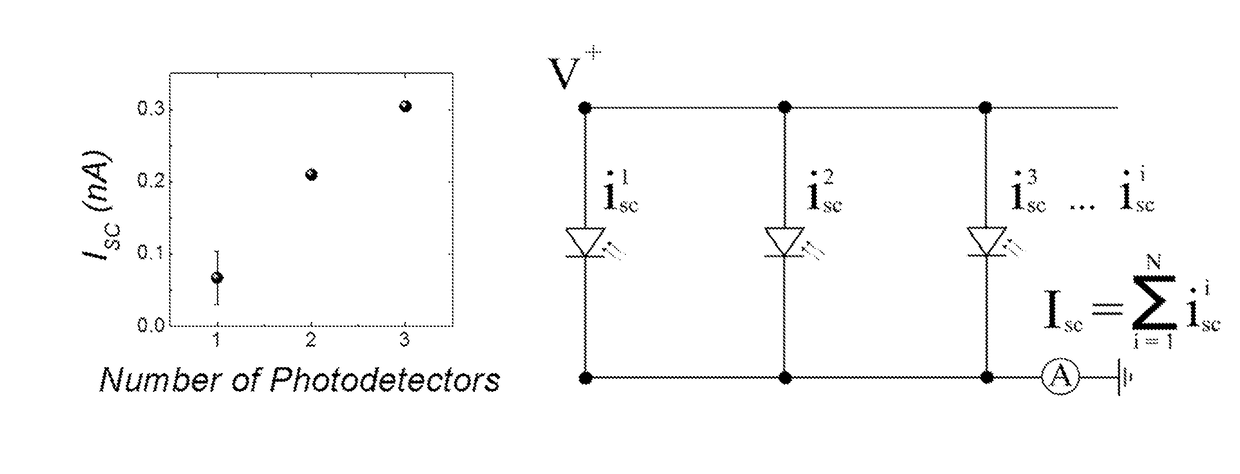
n-Plane Photodetector

[0329]A MoS2 ink with concentration of 0.6 mg / mL was formulated using the method described in Example 3. The UV-Vis spectra of the MoS2 ink before and after PS1 removal are shown in FIG. 28.

[0330]The MoS2 ink was printed onto PEL paper using a Dimatix DMP-2800 inkjet printer to form a rectangle of dimensions 1×1.25 mm with 25 μm drop spacing and 30 print passes.

[0331]A graphene ink with concentration of 0.6 mg / mL was made using the method described in Example 1 and used to print ‘comb like’ electrodes (FIG. 29) over the MoS2 rectangle using 40 print passes and 25 μm drop spacing.

[0332]The resulting device was imaged using an optical microscope and found to have a small electrode spacing<50 μm. (FIG. 38)

[0333]The two graphene electrodes were connected to a Keithley 2400 Sourcemeter and a bias voltage of 60V placed across the device.

[0334]A laser with λ=514.5 nm and power density=0.2 mW / μm2 was used to illuminate the device.

[0335]A photocurrent map of the highligh...


PUM

PropertyMeasurementUnit
surface tensionaaaaaaaaaa
widthaaaaaaaaaa

Abstract

The present invention relates to an ink formulation comprising two-dimensional inorganic layered particles. The ink formulations of the present invention are for inkjet printing. The present invention also relates to a process for the preparation of these ink formulations, to the use of these ink formulations for the production of printed films and tracks comprising the inorganic material, to the films or tracks produced by the inkjet printing of these ink formulations, to devices that comprise these films or tracks, and to systems comprising an array of these devices.

Description

INTRODUCTION[0001]The present invention relates to an ink formulation and, more specifically, to an ink formulation that comprises nanosheets of an inorganic material and which is suitable for inkjet printing. The present invention also relates to a process for the preparation of these ink formulations, to the use of these ink formulations for the production of printed films and tracks comprising the inorganic material, to the films or tracks produced by the inkjet printing of these ink formulations, to devices that comprise these films or tracks, and to systems comprising an array of these devices.BACKGROUND OF THE INVENTION[0002]The advent of graphene (K. S. Novoselov, A. K. Geim, S. V. Morozov, D. Jiang, Y. Zhang, S. V. Dubonos, I.V. Grigorieva and A. A. Firsov, “Electric field Effect in Atomically Thin Carbon Films”Science, Vol. 306, No. 5696, pp. 666-669, 2004) and subsequent discovery of its multitude of superior properties, has led to the identification of many other two-dime...

Claims


Application Information

Patent Timeline
Patent Type & Authority Applications(United States)
IPC IPC(8): C09D11/30H01L31/0224H01L31/112H01L29/45H01L31/032H01L31/103H01L29/24H01L21/02H01L21/4763B41M5/00
CPCC09D11/30H01L31/022408H01L31/112H01L29/45H01L31/032H01L31/103H01L29/24H01L21/02568H01L21/02623H01L21/4763B41M5/0023C01B21/0648C01P2004/24H10K71/135H10K85/20H10K30/81
Inventor MCMANUS, DARYL
Owner UNIV OF MANCHESTER
Why Eureka
Try Eureka