Portable ocular response testing device and methods of use

a testing device and ocular response technology, applied in the field of portable ocular response testing devices, to achieve the effect of being convenient to carry around

Inactive Publication Date: 2018-11-22
OPHTHALIGHT DIGITAL SOLUTIONS INC
View PDF6 Cites 22 Cited by
  • Summary
  • Abstract
  • Description
  • Claims
  • Application Information

AI Technical Summary

Benefits of technology

[0017]One objective of the present invention is to provide an ocular response testing device which is readily portable for performing ocular response tests in a variety of testing environments.

Problems solved by technology

In both instances, the devices are not well suited to be readily portable between various testing locations.
Furthermore, both devices are limited in the conditions which they are able to evaluate.
a. Swinging-Flashlight Test: Briefly, this test is performed in a dimly lit room, using a strong light source. Pupillary reactions are observed as the light shines in one eye. Normally, when either eye is exposed to direct light, both eyes will constrict. In an individual with RAPD, shining light into an unaffected eye will cause both pupils to constrict, while shining light into the affected eye will yield a diminished constrictive response in both eyes. There are significant drawbacks associated with this test. The major drawback is the subjectivity of the examiner's opinion about the variations of pupil size and speed of response to light (which both are important parameters in evaluating the state of RAPD). Also, the unsymmetric test situation for either eye, makes the test procedure unreliable for mild RAPDs. Although the response of each eye to light stimuli should be measured independently and in isolation, the ability of swinging-flashlight test in providing this condition is limited because both patient's eyes should be open to let doctor check each pupil size change. Moreover, the ambient light in the room affects the amount of received light by each eye which makes results prone to error.
b. Brightness Saturation Test (BST): BST is used along with swinging-flashlight test to quantify RAPD. This method is to place a series of neutral density filters in front of the intact eye to change the light intensity, and to repeat the swinging-flashlight test. More particularly, this method is performed by increasing the density of the filters in front of the intact eye until the defective eye's constriction is observed to be the same level as its impaired direct reflex.
c. Color Discrimination Test (CDT): CDT is used along with swinging-flashlight test and BST to quantify RAPD. This method is to place a red object in front of one eye and to ask the patient to choose the most similar color to the object from the color bar in front of the other eye. The amount of discrepancy among the two reds, results in quantification of RAPD. Similarly, due to the subjective and verbal communication between patient and doctor, determination of exact amount of difference between perceived values of the red object by each eye is not quite possible.
The person with color blindness is unable or is limited to see color, or distinguish color differences, under normal lighting conditions.
Unlike the people with normal vision, color blind patients are not able to find a number at all or they see a different number.
Although it is one of the most common color blindness detection tests however, it can not be used for checking young children's vision; because they can not recognize different numbers and correct communication with them is not always possible.
Other than the long time needed to perform this test which makes patients tired, the ambient light may affect the patient's perception of colors and make the results prone to errors.
Several problems such as 1— human errors in measuring pupil size using naked eye, 2— variations in testing condition such as the changes in ambient light, 3— not controlled and non-intentional changes in penlight light intensity due the variations in batteries' charge and etc., resulted in a long sought but unfulfilled need for apparatus, methods and systems that automatically assess and quantify ophthalmologic biomarkers of Marcus-Gunn and color blindness.
Limited access to ophthalmologist due to busy appointments imposes a challenge on getting the high standard health service that patients deserve.
Also, patients who live in remote areas have very limited access to specialists and cannot be routinely checked up.
According to the National Highway Traffic Safety Administration, DUI and alcohol related crashes cause approximately $37 billion in damages annually.
The main problem in performing the test is subjectivity of the results based on the experience of the police officer, the validity of the test results, and the potential of recording the results to be admissible in court.
However, as the tests are commonly being performed partially and in a very subjective manner with no methods of recording the results, other than taking notes, the eye tests have not yet completely demonstrated their actual importance and accuracy in DUI or DWI cases.

Method used


Image

  • Portable ocular response testing device and methods of use
  • Portable ocular response testing device and methods of use
  • Portable ocular response testing device and methods of use

Examples


example 1

Swinging Flashlight Test

[0153]In an aspect, pupillary response scanning device 100 may be configured for performing a swinging flashlight test. FIG. 3A is a logical flow diagram, illustrating one flow 300 of example operations within a swinging flashlight test procedure performed using pupillary response scanning device 100 of the present disclosure. Operations in the flow 300 may include: continuously illuminating both eyes with infrared light from one or more infrared light sources during testing (step 301); capturing at least one reference image of each eye with one or more imaging devices (step 302); illuminating a first eye with visible white light from at least one visible light source in a first eye enclosure for a predetermined duration (step 303); capturing at least one first test image of each eye with one or more imaging devices (step 304); subjecting both eyes to a dark adaptation period under infrared illumination (step 305); illuminating a second eye with visible white...

example 2

Brightness Saturation Test (BST)

[0159]In an aspect, pupillary response scanning device 200 may be configured for performing a BST.

[0160]FIG. 3B is a logical flow diagram, illustrating one flow 310 of example operations within a BST procedure performed using pupillary response scanning device 100 of the present disclosure. Operations in the flow 310 may include: identifying an affected eye and a healthy eye with a swinging flashlight test (step 311) that may be performed by exemplary operations of the flow 300 of FIG. 3A; illuminating the affected eye with visible white light from at least one visible light source for a predetermined duration (step 312); capturing at least one first test image of the affected eye that is subjected to direct light application (step 313); subjecting both eyes to a dark adaptation period under infrared illumination (step 314); illuminating the healthy eye with visible white light from at least one visible light source with a predetermined initial intens...

example 3

Color Discrimination Test (CDT)

[0165]In an aspect, pupillary response scanning device 100 may be configured for performing a CDT. FIG. 3C is a logical flow diagram, illustrating one flow 321 of example operations within a CDT procedure performed using pupillary response scanning device 100 of the present disclosure. Operations in the flow 321 may include: identifying an affected eye and a healthy eye with a swinging flashlight test (step 322) that may be performed by exemplary operations of the flow 100 of FIG. 3A; illuminating the affected eye with visible red light from at least one visible light source for a predetermined duration (step 323); capturing at least one first test image of the affected eye that is subjected to direct light application (step 324); subjecting both eyes to a dark adaptation period under infrared illumination (step 325); illuminating the healthy eye with visible red light from at least one visible light source with a predetermined initial intensity (step ...


PUM


Abstract

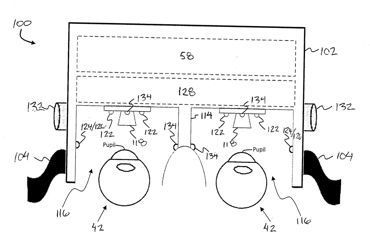
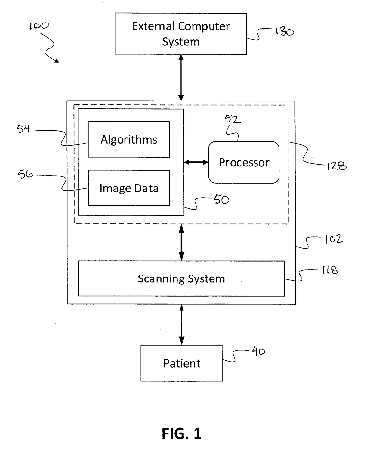
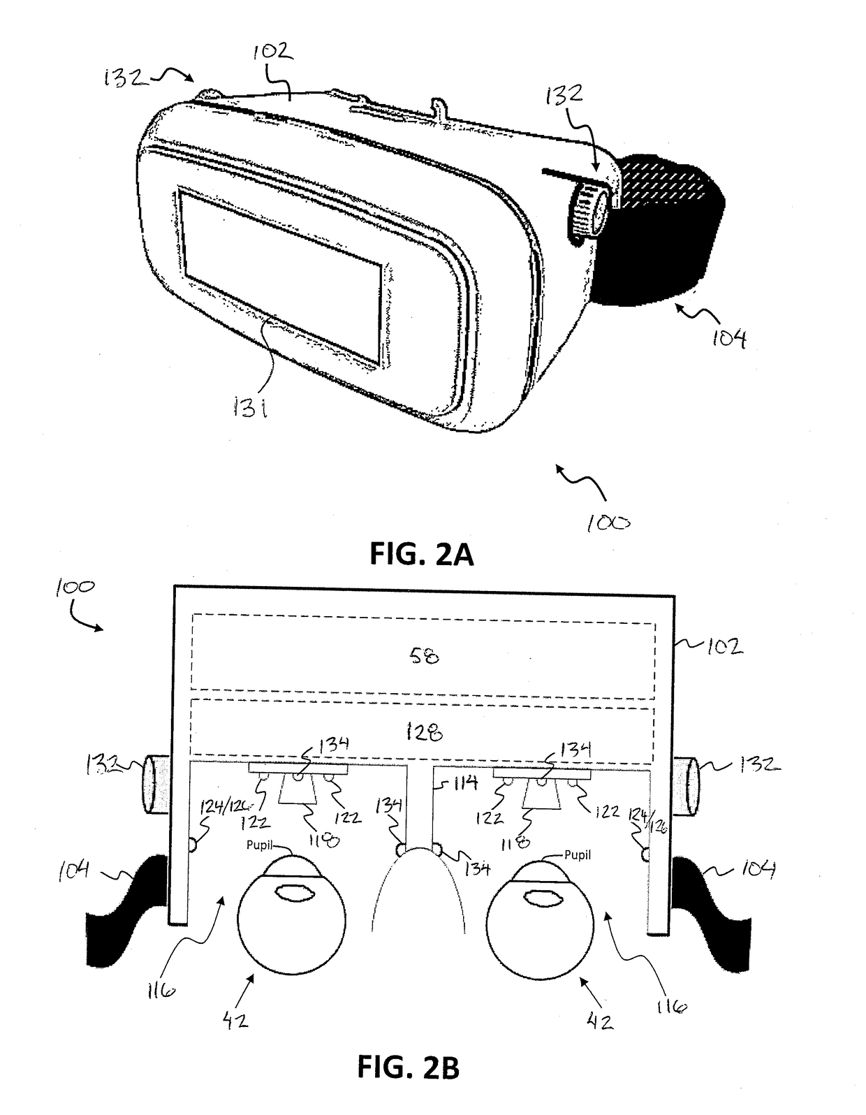
A portable ocular response testing device includes a portable housing, a plurality of lights for generating visible light within two eye spaces of the portable housing, a controller for operating the lights according to a prescribed pattern, and an imaging system to capture images of the eyes under varying lighting conditions to evaluate an ocular response of a user to the lighting conditions. In some instances, the portable device is used in the field of ophthalmology for complete assessment of optic nerve defects producing Marcus-Gunn pupil, detection and quantification of color blindness, and detection and follow up of eye abnormalities. In other instances, the device is adapted for screening of driving under influence (DUI) or Driving While Intoxicated (DWI) by performing multiple eye tests resulting in field screening of DUI or DWI cases.

Description

FIELD OF THE INVENTION[0001]The present invention relates a portable ocular response testing device including a portable housing, a plurality of lights for generating visible light within two eye spaces of the portable housing, a controller for operating the lights according to a prescribed pattern, and an imaging system to capture images of the eyes under varying lighting conditions to evaluate an ocular response of a user to the lighting conditions. More particularly, in some instances the present invention relates to a portable device in the field of ophthalmology for complete assessment of optic nerve defects producing Marcus-Gunn pupil, detection and quantification of color blindness, and detection and follow up of eye abnormalities. In another instance, the present invention relates generally to a device for screening of driving under influence (DUI) or Driving While Intoxicated (DWI) by performing multiple eye tests resulting in field screening of DUI or DWI cases.BACKGROUND[...

Claims


Application Information

Patent Timeline
Patent Type & Authority Applications(United States)
IPC IPC(8): A61B5/18A61B3/00A61B3/113A61B3/14A61B5/00G06K9/00A61B3/18
CPCA61B5/18A61B3/0008A61B3/0058A61B3/0091A61B3/113A61B3/145A61B5/4863G06K9/0061A61B3/18A61B5/746A61B5/4845A61B3/066A61B3/112A61B5/163A61B3/14G06V40/193
Inventor ROSHAN, YASER MOHAMMADIANVEJDANI, AMIRHOSSEINHAMIDI, FARZADKOHAN, EHSAN DANESHIRASHIDI, YOUNES
Owner OPHTHALIGHT DIGITAL SOLUTIONS INC
Why Eureka
Try Eureka