Frequency-selective damper valve, and shock absorber and piston having such valve

a frequency selective and damper valve technology, applied in vibration dampers, liquid based dampers, shock absorbers, etc., can solve the problems of deteriorating the performance of the frequency selective valve, requiring relatively a large amount of space, and not easily obtaining the desired relation between closing force and tim

Active Publication Date: 2018-11-22
KONI BV
View PDF4 Cites 6 Cited by
  • Summary
  • Abstract
  • Description
  • Claims
  • Application Information

AI Technical Summary

Benefits of technology

[0013]a variable volume chamber, the movable valve body interacting with the variable volume chamber such that movement of the movable valve body and a change in volume of the variable volume chamber are interrelated, wherein the variable volume chamber comprises an outlet opening, in operation, downstream of the controlled valve assembly and does not comprise an opening upstream of the controlled valve assembly with respect to the controlled fluid flow in the controlled flow channel, the outlet opening providing a flow resistance, and a fluid pressure upstream of the controlled valve assembly with respect to the controlled fluid flow acting on the movable valve body to induce a force on the movable valve member in a direction to increase a fluid pressure in the variable volume chamber and to decrease a volume of the variable volume chamber by fluid flow from the variable volume chamber through the outlet opening, which allows an interrelated movement of the movable valve body.
[0014]The damper valve of the invention can readily be implemented such as to act in opposite directions. It further allows to provide for a well-defined relation of fluid flow and pressure with regard to closing position and closing velocity of the damper valve. Performance is very robust and very independent of manufacturing tolerances. The design is very simple and allows implementation in a very limited amount of space.
[0017]In an embodiment the controlled valve assembly is configured to have spring-like behaviour and to exert a force on the movable valve body in a direction to move the movable valve body back to a neutral position when the movable valve body has moved from the neutral position. Especially such embodiment allows to effectively provide an equilibrium position at a range of fluid pressures upstream of the controlled valve at a closed configuration of the controlled valve assembly. The controlled valve assembly will open again at a further pressure increase.
[0035]a second main channel and a second main non-return valve associated with the second main channel such that the second main channel and second main valve allow and damp a second main fluid flow from the first to the second cylinder chamber,

Problems solved by technology

However, a desired relation between closing force and time is not easily obtained, if at all, in the presently known configurations of frequency selective valves.
Having the control chamber pressure maintained at some level above neutral strongly deteriorates the performance of the frequency selective valve.
It requires two known configurations to obtain frequency-selective damping in opposite directions, which requires relatively a large amount of space.
In itself, a one-directional known frequency selective damping valve already requires quite some space, which may make application of such valve difficult.

Method used


Image

  • Frequency-selective damper valve, and shock absorber and piston having such valve
  • Frequency-selective damper valve, and shock absorber and piston having such valve
  • Frequency-selective damper valve, and shock absorber and piston having such valve

Examples


Embodiment Construction

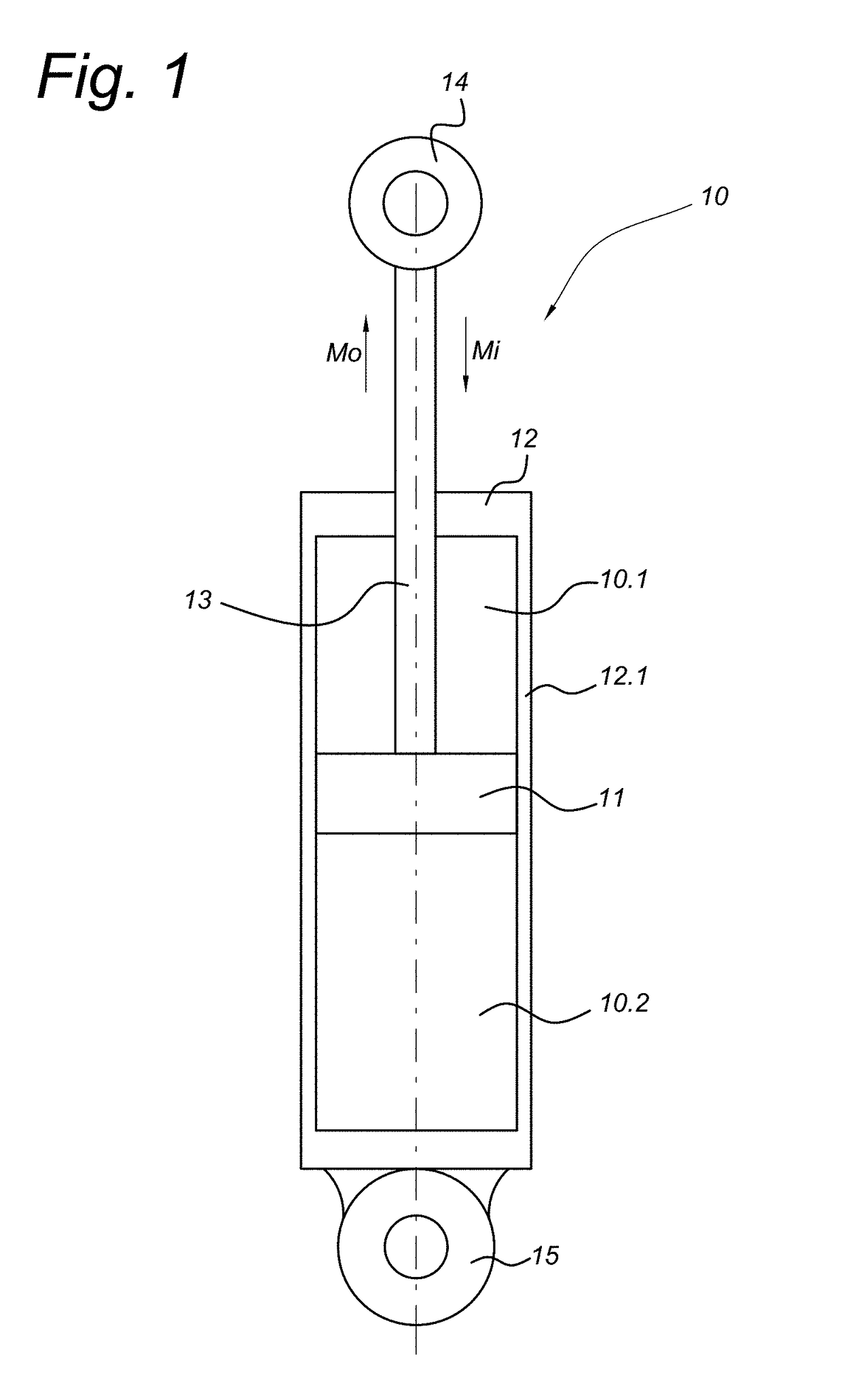
[0084]FIG. 1 schematically shows a shock absorber or damper 10 according to the invention. The damper comprises a cylinder 12 and a piston 11 that can move within the cylinder in inward and outward directions with respect to the cylinder. The direction of movement of the inward and outward strokes of the piston are indicated by the arrows labeled Mi and Mo, respectively. The piston seals against the cylindrical wall 12.1 of the cylinder and divides the cylinder in a first or upper cylinder (or damper) chamber 10.1 and a second or lower cylinder (or damper) chamber 10.2. A piston rod 13 attached to the piston 11 is in a sealing fashion guided through a top wall of the cylinder 12. The damper can be attached by its piston and cylinder attachment arrangements 14, 15 to, for instance, parts of a car to damp relative movements. Damping is achieved by influencing a fluid flow in between first and second cylinder chambers at piston movement within the cylinder by, for instance, an arrangem...


PUM


Abstract

A frequency-selective damper valve includes a controlled flow channel providing a fluid connection between a first and second valve sides; a controlled valve assembly in a controlled flow channel; a movable valve body acting on the controlled valve assembly; and a variable volume chamber, the movable valve body interacting with the variable volume chamber such that movement of the movable valve body and a change in volume of the variable volume chamber are interrelated. The variable volume chamber includes an outlet opening, in operation, downstream of the controlled valve assembly and does not include an opening upstream of the controlled valve assembly with respect to a controlled fluid flow in the controlled flow channel, the outlet opening providing a flow resistance.

Description

FIELD OF THE INVENTION[0001]The invention relates to a frequency-selective damper valve having a controlled flow channel and a controlled valve assembly provided in the controlled flow channel.BACKGROUND OF THE INVENTION[0002]Dampers, or shock absorbers, are well known and widely applied in, for instance, a variety of vehicles like cars, truck, buses and trains. The dampers are designed to provide a desired damping behavior between parts moving with respect to one another. Damping can be chosen to be stiff or soft by the specific design of the damper. More advanced dampers have been proposed, which provide a frequency-selective damping behavior to the damper. A frequency-selective damping valve can be added to the damper to provide a desired frequency-selective damping behavior. Such frequency-selective damping valve can be added to or incorporated into known damper configurations to provide additional frequency selectivity. On the other hand, such frequency-selective dampers can al...

Claims


Application Information

Patent Timeline
Patent Type & Authority Applications(United States)
IPC IPC(8): F16F9/512F16F9/34F16F9/36
CPCF16F9/5126F16F9/34F16F9/362F16F9/3482F16F9/3485F16F9/16
Inventor DE KOCK, PAUL
Owner KONI BV
Why Eureka
Try Eureka