Unlock instant, AI-driven research and patent intelligence for your innovation.
Rigid-collision-free transmission line spacer clamp connection structure
Active Publication Date: 2018-11-22
STATE GRID HENAN ELECTRIC POWER ELECTRIC POWER SCI RES INST +3
View PDF3 Cites 2 Cited by
Summary
Abstract
Description
Claims
Application Information
AI Technical Summary
This helps you quickly interpret patents by identifying the three key elements:
Problems solved by technology
Method used
Benefits of technology
Benefits of technology
The present invention provides a spacer clamp connection structure that prevents damage to the spacer due to galloping of the conductor and reduces damage to the spacer by using a soft connection structure instead of a hard connection structure. The structure includes a connecting rod and clip that form an integral structure to prevent dropping of the rubber gasket and bending and deformation of the clip. A small amount of energy generated during aeolian vibration can be dissipated on the elastic gasket. The connection structure also includes a rotating joint rubber gasket that can be adjusted at an angle and a limiting groove and block mechanism to ensure the position of the rubber gasket is limited. The connection structure prevents rigid impact and reduces damage to the spacer due to galloping of the conductor by using elastic impact. The spacer frame is of a double-frame-board structure and rivets are arranged in the rivet holes to prevent bolt fasteners from dropping from the spacer frame.
Problems solved by technology
However, the existing rubber gasket is only provided with one cylindrical clamping block, and the spacer often drops out of the spacer clip during transport, installation and use.
During galloping of the conductor, subspan oscillation and conductor vibration in other forms, the spacer is subject to the torsional force and bending forces from different directions, and the hard connection structure suffers from severe collision, which is very likely to cause abrasion or even rupture and damage of the limiting structure at the joint between the clamp and the frame.
If galloping occurs again in the line after the spacer is damaged, it may result in broken strands or abrasion of the conductor near the spacer, and may even lead to rupture of the conductor when it is serious, thus causing great harm to the line operation.
Method used
Image
Click on the blue label to locate the original text in one second.
Reading with bidirectional positioning of images and text.
Examples
Embodiment Construction
[0029]The present invention is described below in detail in conjunction with the drawings and embodiments.
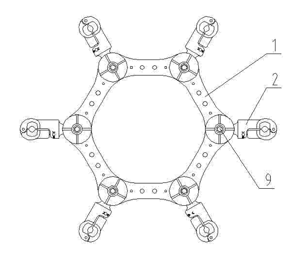
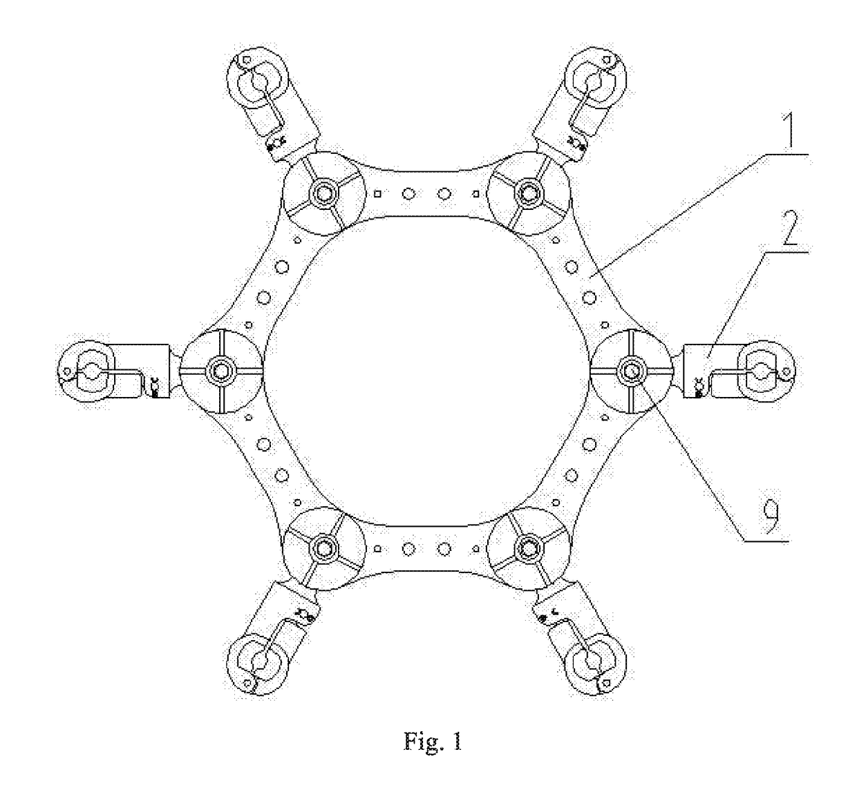
[0030]As shown in FIGS. 1 to 8, a rigid-collision-free transmission line spacer clamp connection structure of the present invention includes a spacer frame 1, rotating joint rubber gaskets and spacer connecting clamps 2, the spacer frame 1 being uniformly provided with a plurality of rotating joint slots 8, each of which is rotationally connected with a spacer connecting clamp 2 therein.
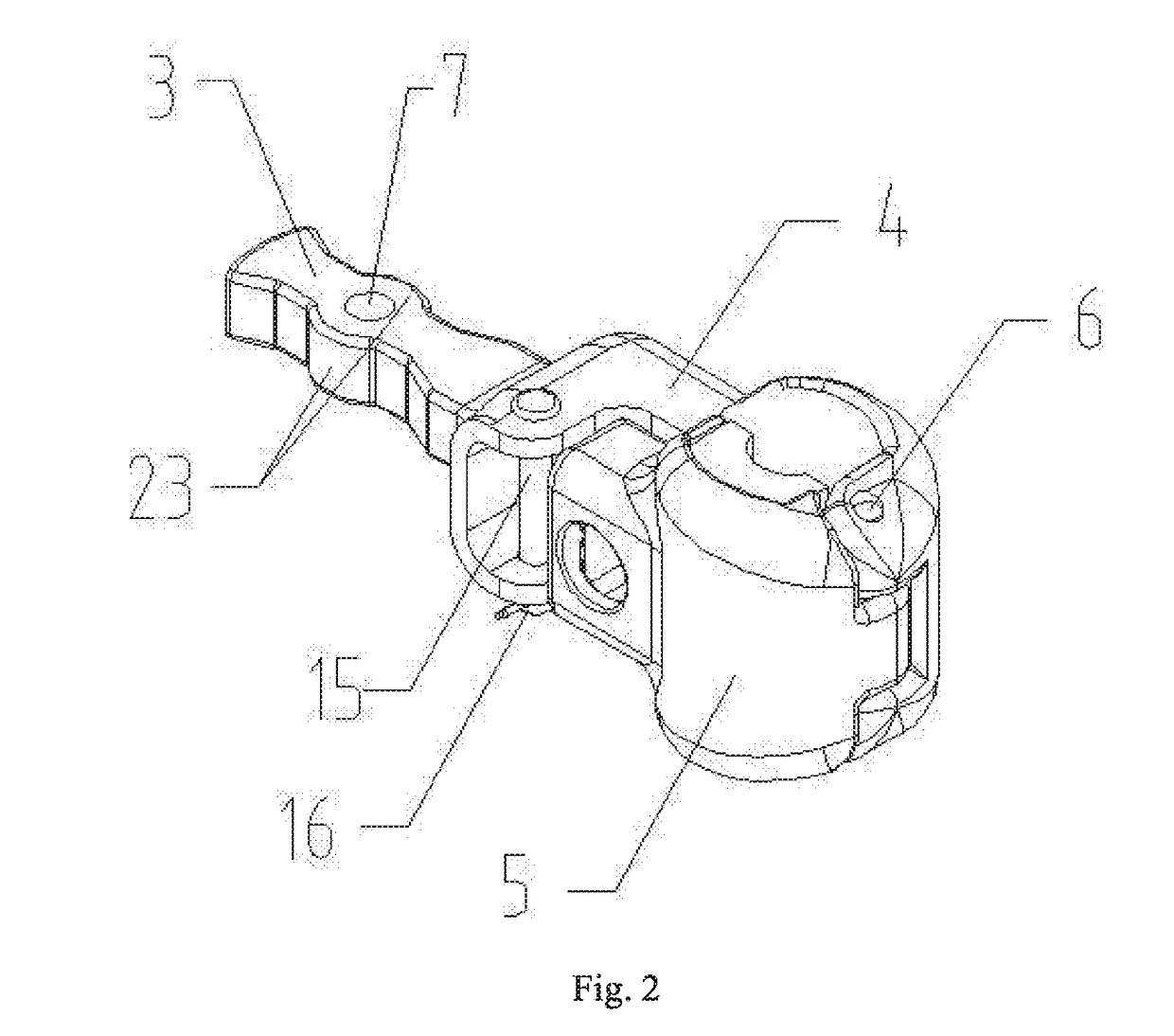
[0031]As shown in FIG. 2, the spacer connecting clamp 2 includes a connecting rod 3, a clip 4 and a clip cover plate 5, the connecting rod 3 and the clip 4 forming an integral structure, the clip 4 being arranged at a front end of the connecting rod 3, a front end of the clip 4 and a front end of the clip cover plate 5 being hinged via a clip rotating shaft 6, the clip 4 and the clip cover plate 5 being each provided with an elastic material 19 at the inner side, the elastic material 19 being cla...
PUM
Abstract
A rigid-collision-free transmission line spacer clamp connection structure includes a spacer frame, rotating joint rubber gaskets and spacer connecting clamps, the spacer frame being uniformly provided with a plurality of rotating joint slots that are rotationally connected with spacer connecting clamps, adopting a “spacer frame, rotating joint rubber gasket and spacer connecting clamp body tail” connection form. The spacer connecting clamp has a connecting rod and a clip, the connecting rod being provided with a connecting rod mounting hole at a rear end and the rotating joint slot being provided with a rotating joint rubber gasket and a spacer connecting clamp rotating shaft therein. The spacer connecting clamp rotating shaft penetrates through the connecting rod mounting hole and a rotating joint rubber gasket mounting hole.
Description
BACKGROUND OF THE INVENTION1. Field of the Invention[0001]The present invention relates to a protection fitting for an overhead transmission line, and in particular relates to a rigid-collision-free transmission line spacer clamp connection structure.2. Description of the Prior Art[0002]In an overhead transmission line, a spacer serves to prevent flagellation between sub-conductors in a bundle and resist aeolian vibration and subspan oscillation, etc. The spacer mainly includes a frame body and a connecting clamp connected to a frame. A clip of the connecting clamp is used for clenching the sub-conductors in the bundle, and the clip is rotated a certain angle along a tangential direction under the action of an axial torsional force of the conductor through a limiting structure at the joint between the frame body and the connecting clamp.[0003]According to the power industry standards Requirements and Tests for Overhead Line Spacers (DL / T 1098-2009), a spacer should have certain mech...
Claims
Application Information
Patent Timeline
Application Date:The date an application was filed.
Publication Date:The date a patent or application was officially published.
First Publication Date:The earliest publication date of a patent with the same application number.
Issue Date:Publication date of the patent grant document.
PCT Entry Date:The Entry date of PCT National Phase.
Estimated Expiry Date:The statutory expiry date of a patent right according to the Patent Law, and it is the longest term of protection that the patent right can achieve without the termination of the patent right due to other reasons(Term extension factor has been taken into account ).
Invalid Date:Actual expiry date is based on effective date or publication date of legal transaction data of invalid patent.

