

Electrode assembly and flow battery with improved electrolyte distribution
- Summary
- Abstract
- Description
- Claims
- Application Information
AI Technical Summary
Benefits of technology
Problems solved by technology
Method used
Image

Examples
Embodiment Construction
[0061]Certain terminology is used in the present description and is intended to be interpreted according to the definitions provided below. In addition, terms such as “a” and “comprises” are to be taken as open-ended.
[0062]Herein, in a quantitative context, the term “about” should be construed as being in the range up to plus 20% and down to minus 20%.
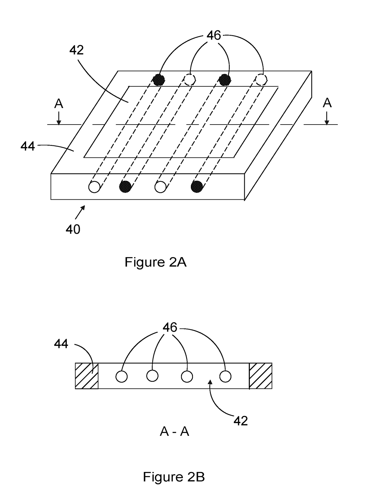
[0063]The term “entirely embedded” is used herein to describe a distributor tube that is placed within the porous material of the electrode such that outer surface of the tube is surrounded by electrode material.
[0064]The term “partially embedded” is used herein to describe a distributor tube that is placed within the porous material of the electrode with at least a portion of the outer surface of the distributor tube not surrounded by electrode material.
[0065]FIG. 2A shows a schematic view of an electrode assembly according to a preferred embodiment of the invention. Electrode assembly 40 comprises a porous electrode material 42 surro...
PUM
 Abstract
Description
Claims
Application Information