

Laminate for reducing flow resistance and manufacturing method therefor
a technology of flow resistance and laminate, applied in the direction of lubricant composition, mechanical equipment, coatings, etc., can solve the problems of environmental pollution, difficult to apply the same to a large area, microbial adhesion, etc., and achieve the effect of small shear force, excellent effect and superior cleaning
Active Publication Date: 2018-12-06
PUSAN NAT UNIV IND UNIV COOPERATION FOUND
View PDF2 Cites 2 Cited by
- Summary
- Abstract
- Description
- Claims
- Application Information
AI Technical Summary
Benefits of technology
The present invention is based on the fact that penguins have an air layer between their feathers on land before they enter the water. This air layer reduces friction and flow resistance when the penguins move through the water. The invention utilizes this principle by forming an air layer on the surface of an object when it contacts a fluid. This air layer generates a strong slip, resulting in a small shear force and a near-zero flow friction resistance.
Problems solved by technology
However, since it requires precise processing of less than 200 microns, it is difficult to apply the same to a large area, and there is a problem of including microbial adhesion.
However, since the polymer must be continuously sprayed on the surface, there is a problem of environmental pollution.
However, in the case of ships, there are problems such as loss of buoyancy and propulsion, generation of cavities due to bubbles, mounting of actuators for compressed air injection, and so on.
Thus, these techniques have not been commercialized to date.
Method used
View moreImage
Smart ImageViewing Examples

Examples
example 1
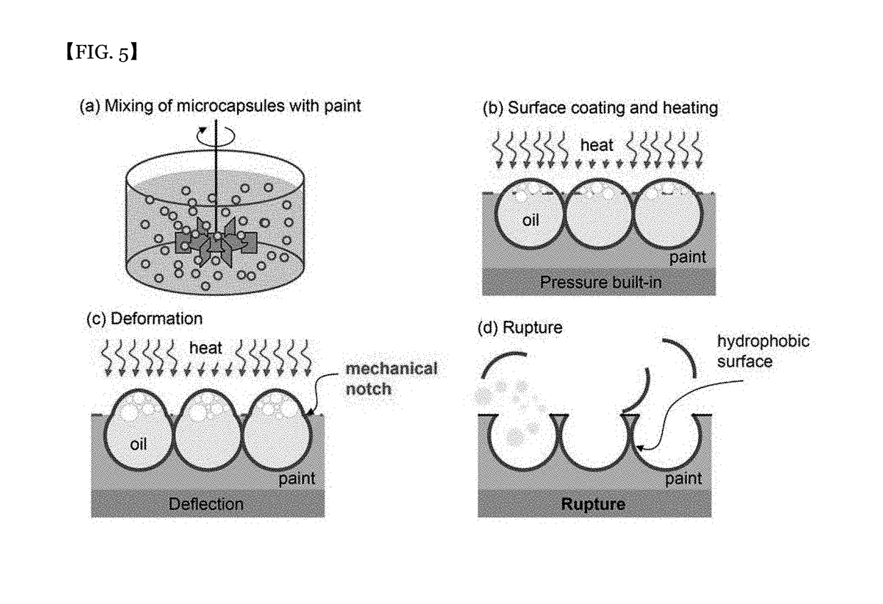
[0053]The oil-contained micro-capsule and PVA (polyvinyl alcohol) were dispersed at a ratio of 1:1. The micro-capsules were well dispersed in the PVA. This capsule-dispersed PVA was spin-coated onto the silicon surface. The specific gravity of the oil was smaller than the specific gravity of the PVA, so that the micro-capsule floated toward the PVA surface, and the PVA was cured after a certain time. See the SEM picture of FIG. 6. As shown in the SEM photograph of FIG. 7, the shell of the micro-capsule was ruptured and a surface portion of the PVA having the partially opened micro-cavities was formed.
Login to View More PUM
| Property | Measurement | Unit |
|---|---|---|
| flow-resistance | aaaaa | aaaaa |
| length | aaaaa | aaaaa |
| depth | aaaaa | aaaaa |
Abstract
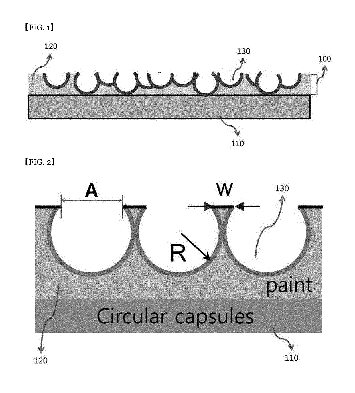
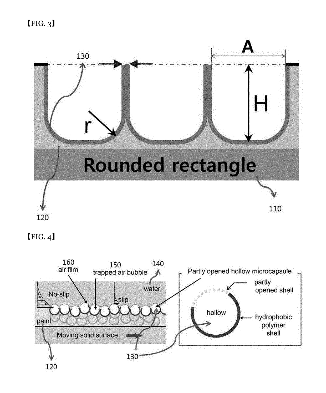
There is provided a flow-resistance reducing laminate comprising: a substrate; and a flow-resistance reducing layer formed on the substrate, wherein the flow-resistance reducing layer has a surface portion facing a liquid, wherein a flow interface is formed between the liquid and the laminate upon relative movement between the liquid and the laminate, wherein the flow-resistance reducing layer is configured such that an air layer defines the flow interface.
Description
BACKGROUNDField of the Present Disclosure[0001]The present invention relates to a surface structure of an object for reducing the flow resistance generated between a fluid and an object during movement of the fluid or moving the object, and a method of manufacturing such a structure.Discussion of Related Art[0002]The resistance due to flow includes the frictional resistance due to the friction generated by the surface state of the object and the shape resistance due to the pressure distribution caused by the shape of the object, and such a flow resistance is a natural phenomenon inevitably generated.[0003]Marine, offshore plants, petroleum pipelines and submarines are consuming enormous amounts of fuel to overcome this flow resistance, and, thus, the need to reduce this flow resistance is fully appreciated.[0004]For logistics transporters, they consume about 200 trillion won of fuel per year. In particular, the flow resistance corresponds to 80% or more of the energy consumption at ...
Claims
Login to View More Application Information
Patent Timeline
 Patent Type & AuthorityApplications(United States)
IPC IPC(8): C10M111/04B05D1/00B05D3/02C10M101/00C10M107/24
CPCC10M111/04B05D1/005B05D3/0254C10M101/00C10M107/24C10M2203/003C10M2209/043C10N2250/16C10N2250/08B05D5/02B05D5/08F15D1/10B32B5/18B32B3/26F15D1/00C10N2050/08C10N2050/12
InventorGO, JEUNG SANGPAIK, HYUN-JONGKIM, KYUNG CHUNYOON, SANG YOUL
OwnerPUSAN NAT UNIV IND UNIV COOPERATION FOUND