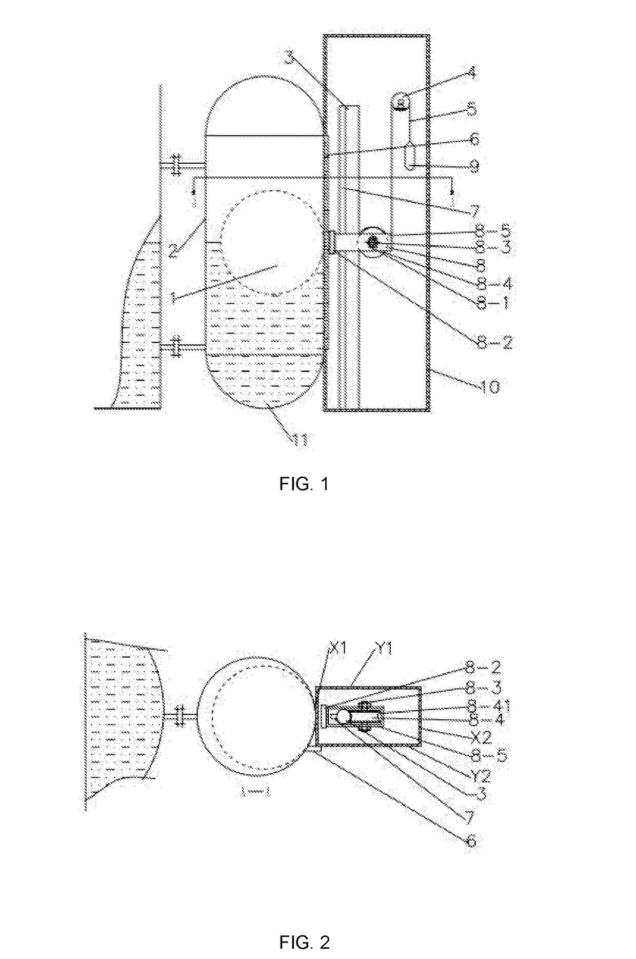
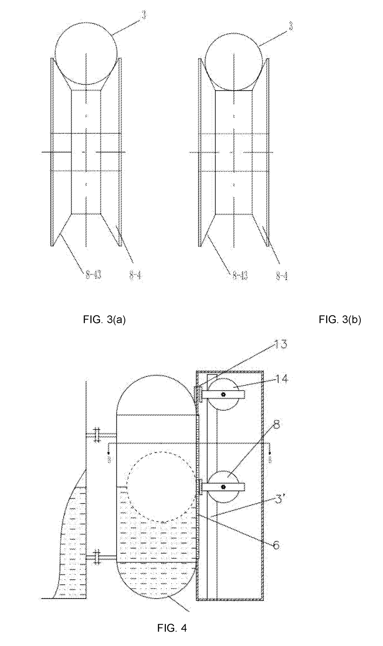
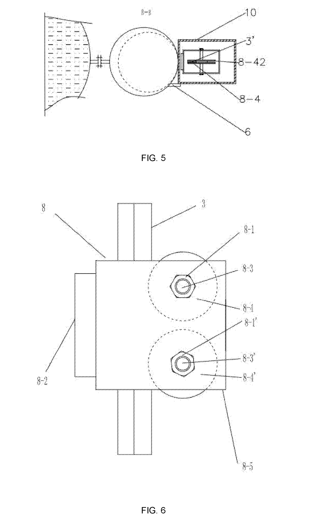
The structure of the magnetic flap (column) type is relatively complex, and it is easy to appear garbled.
In addition, the magnetic steel in the ball float still has the problem of high temperature demagnetization, which affects its long-term use, such as, For the imported magnetic ball float liquid liquidometer, although it is resistant to high temperature, the ball float thereof has to be replaced because of the demagnetization of the magnetic steel therein after 4-5 years.
In addition, glass plate level gauges or two-color
water level gauges cannot be insulated, resulting in
high energy consumption.
However, it has the following shortcomings: Both the floater and the moving indicator are sliding friction, resulting in a large
coefficient of friction and large frictional forces that affect the accuracy and sensitivity of the measurement, and wherein the instrument is even unusable.
However, it also has the shortcomings of what the previous patent has, that is, because of the large friction, the accuracy and sensitivity of measurement are affected, so that the instrument is unusable.
Its shortcomings lie in: 1. The floater is sliding friction, which results in large
friction coefficient and friction, which affects the accuracy and sensitivity of the measurement.
7, the level gauge better solves the application of
high pressure boilers, but the magnetic car needs 4 wheels and other components, otherwise the moving indicator will be deflected or shaken up and down and can not be used, which makes the structure complex, Secondly, the weight of the magnetic vehicle is increased, thereby increasing the load of the float, which corresponds to an increase in the weight of the float, which is difficult to satisfy the use in high-temperature high-pressure or high-pressure low-density medium applications, and the remote
signal is discontinuous; meanwhile, the sliding friction between the floater and the floater chamber thereof has a large
friction force described above, and then affects the accuracy and sensitivity of the measurement.
Some of the existing liquid level gauges mentioned above have high unsafe risks due to the
high surface temperature, such as easy-to-scald-people, or fire or explosion which caused by flammable and explosive media.
Another example as China Patent ZL200910219684.3, wherein the floater-type level gauge with a
buoy is used in a high-temperature high-pressure or high-pressure low-density medium applications, the structure of the
buoy is complicated, and the manufacturing cost tends to be high.
With many parts and components, the
failure rate is high, which affects the reliability of use and leads to high maintenance costs.
In addition, the installation of magnetic steel in the ball float is restricted by the high temperature demagnetization thereof, so that The two hemispherical shells of the ball float cannot be welded and thus making the ball-float-manufacture difficult.
The problem of high temperature demagnetization do exist with the magnetic steel thereof when using.
Similarly, there is the same problem as described above for a float level gauge with an on-site indication in the
Chinese patent ZL200910219681.
Again as in
Chinese patent application CN103411652, the disclosed floater is non-spherical and has a large frictional force and has similar problems to the aforementioned patents.
Although the center of gravity of the oil mark holder of this structure is below, it is difficult to ensure that the oil mark holder is vertical, that is, the oil marker holder can easily deviate gradually from its original position in multiple up and down movements.
Even so, it is still difficult to ensure that the axis of the axis thereof is horizontal, that is, it is difficult to ensure that the up-and-down motion of the moving indicator is vertical.
In fact, it will be gradually deviate in the process of using.
Otherwise, the possibility of deviation increases or the distance of deviation increases, that is, there is a problem of accuracy or reliability.
1. High friction, significant
hysteresis, low accuracy: After many times of
relative motion tests between various imported linear bearings and various imported linear guides, the friction between linear bearings and linear guides is an unavoidable issue. The friction between domestic linear bearings and linear guides is greater, and none of the corresponding level gauges is very sensitive, with low accuracy and large
hysteresis. The inventor has proved by experiments that the upper
lag is 3 mm and the backlash is 8 mm. And the linear bearing itself is heavier, it will inevitably increase the weight of the moving indicator. Therefore more magnetic force to couple is required. And then the mechanical
friction force is further increased, the
buoyancy of the ball float needs to be larger, and all these are to result in more problems accordingly. High cost: Imported linear bearings are about 50 yuan each, linear guides made of aluminum
alloy is about 6-7 yuan per meter, and the imported is about 100 yuan per meter. When the range is large, the proportion of the total cost is larger. This does not include other parts on the moving indicator. The rigidity of the guide rail is poor, and the rigidity of the cylindrical linear guide matched with the cylindrical linear bearing decreases with the length of itself. When the moving indicator and the ball float are under the effect of the magnetic
coupling force, the guide rail will bend toward the ball float chamber. too much to be
usable when the range is too large. This kind of guide rail can not improve its rigidity by installing accessories, otherwise it can not be used. Unless straight line bearings is installed. And if the rigidity of the guide rail need to be increased, the
diameter of the guide rail itself must be increased. This will inevitably increase the weight of the linear bearing, which not only would further increase the mechanical
friction force, but also would cause the ball float to sink into the liquid and even to be unusable because of the increase in weight. Too many guide rails joints: since the matching accuracy between linear guide rails and linear bearings is very high, and the linear guide is precision-machined subject to the requirements of the rigidity of the guide rail, each guide rail can not be processed very long. When the measurement range of the liquid level is large, a plurality of guide rails are required to be linked together, and the
coupling between the ends of the guide rails must ensure the accuracy. And this is difficult. Otherwise, the linear bearing might be stuck at the junction of the two guide rails. On the other hand, increasing the rigidity of the guide rail by
diameter thereof to decrease of the number of the joints, will inevitably increase the size of the linear bearing, thereby increasing the weight of the moving indicator. And this load will result in sinking the ball float into the liquid and making the level gauge unusable. 5 Unable to repair the bearing. The structure of the linear bearing itself determines that it is difficult to clean once entering the impurities. In that case it must be updated and thus the cost will be further increased.
Magnetic ball float level gauges imported from Europe and the United States and other countries are expensive, 5-10 million yuan each.
It not only has the problem of not being able to withstand high temperatures and
high pressure at the same time, but also has the problem of demagnetization at high temperatures thus after using several years, the magnetic ball float will need to be replaced.
It can be seen that the cost of it is too high.


