
An ultrasound imaging system probe and system, and an imaging method

an ultrasound imaging system and probe technology, applied in the field of ultrasound imaging system probes and whole systems, can solve the problems of insufficient generation of proper images, insufficient resolution of wave shapes, and increased cost of existing methods, and achieve the effect of higher resolution

Active Publication Date: 2018-12-06
KONINKLJIJKE PHILIPS NV
View PDF0 Cites 1 Cited by
  • Summary
  • Abstract
  • Description
  • Claims
  • Application Information

AI Technical Summary

Benefits of technology

The invention uses band-pass sigma-delta ADCs, which are flexible and programmable. The ADCs have programmable center frequency and band pass, which can be accurately tuned for the desired frequency band. This allows the system to process only the desired frequency band without introducing noise from outside the band. The analog to digital converter has programmable clock frequency and DAC scalability. The center of the pass band of the tunable band pass filter matches the transmitted ultrasound frequency or a desired harmonic. This enables the system to zoom in a band with higher resolution without chaining the noise performance of the building blocks of the ADC.

Problems solved by technology

The high pressure portion of the wave travels faster than low pressure portions resulting in distortion of the shape of the wave.
For example, it is known to use the second harmonic to produce the image as the subsequent harmonics are of decreasing amplitude and hence insufficient to generate a proper image.
It becomes an even more interesting imaging method when higher frequencies are used, because the existing methods become proportionally more complex and costly.
A problem with ultrasound imaging systems is the signal to noise of the received information.
This is improved by providing earlier analog to digital conversion (for a digital signal, connectivity and signal processing are more robust to noise and interference) but this gives rise to higher power consumption of the receiver circuitry.

Method used


Image

  • An ultrasound imaging system probe and system, and an imaging method
  • An ultrasound imaging system probe and system, and an imaging method
  • An ultrasound imaging system probe and system, and an imaging method

Examples


Embodiment Construction

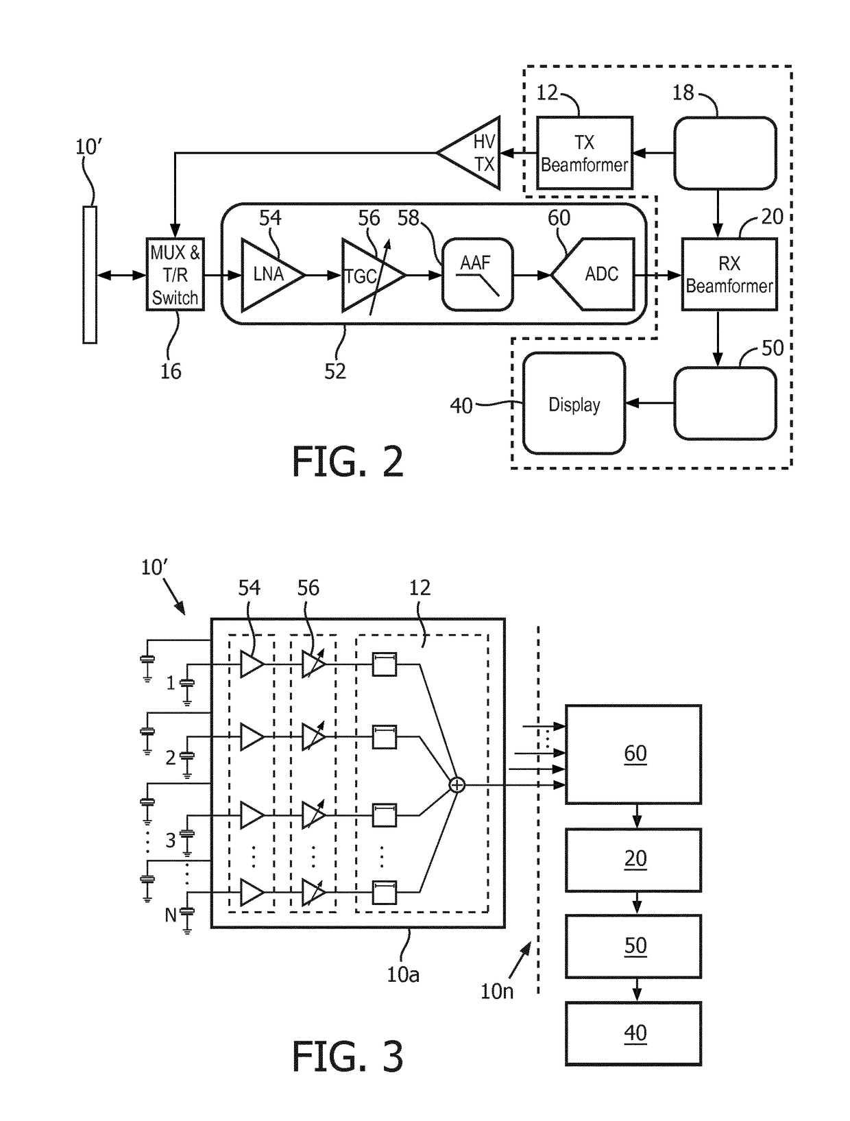
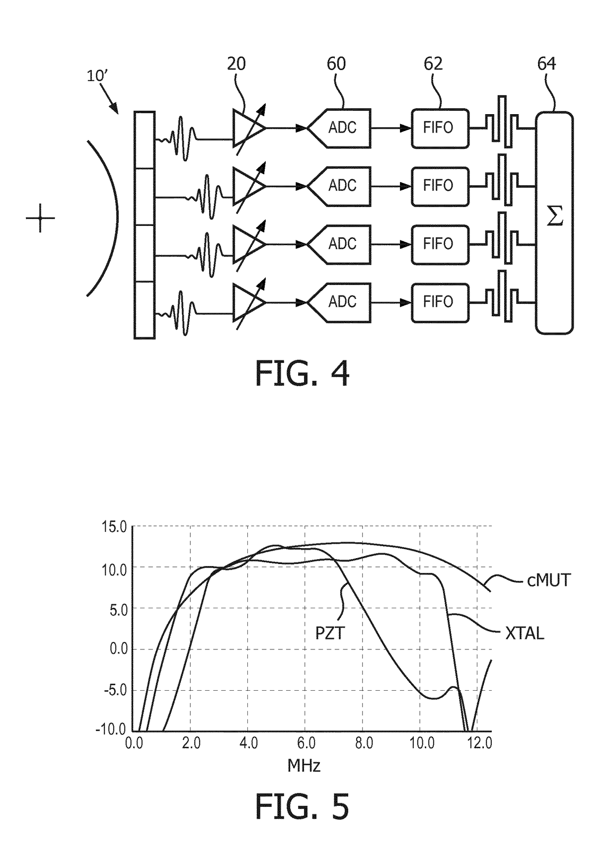
[0049]The invention provides an ultrasound imaging system probe which comprises an imaging transducer head and a reception circuit for processing received reflected ultrasound signals. The reception circuit comprises an analogue to digital sigma delta converter which comprises a closed loop which comprises a tunable band pass filter. This enables the analog to digital converter to process only the desired frequency band. The ADC conversion bandwidth and effective number of bits (ENOB) are in this way programmable giving a more efficient probe design, and also enabling analog to digital conversion early in the signal processing chain.

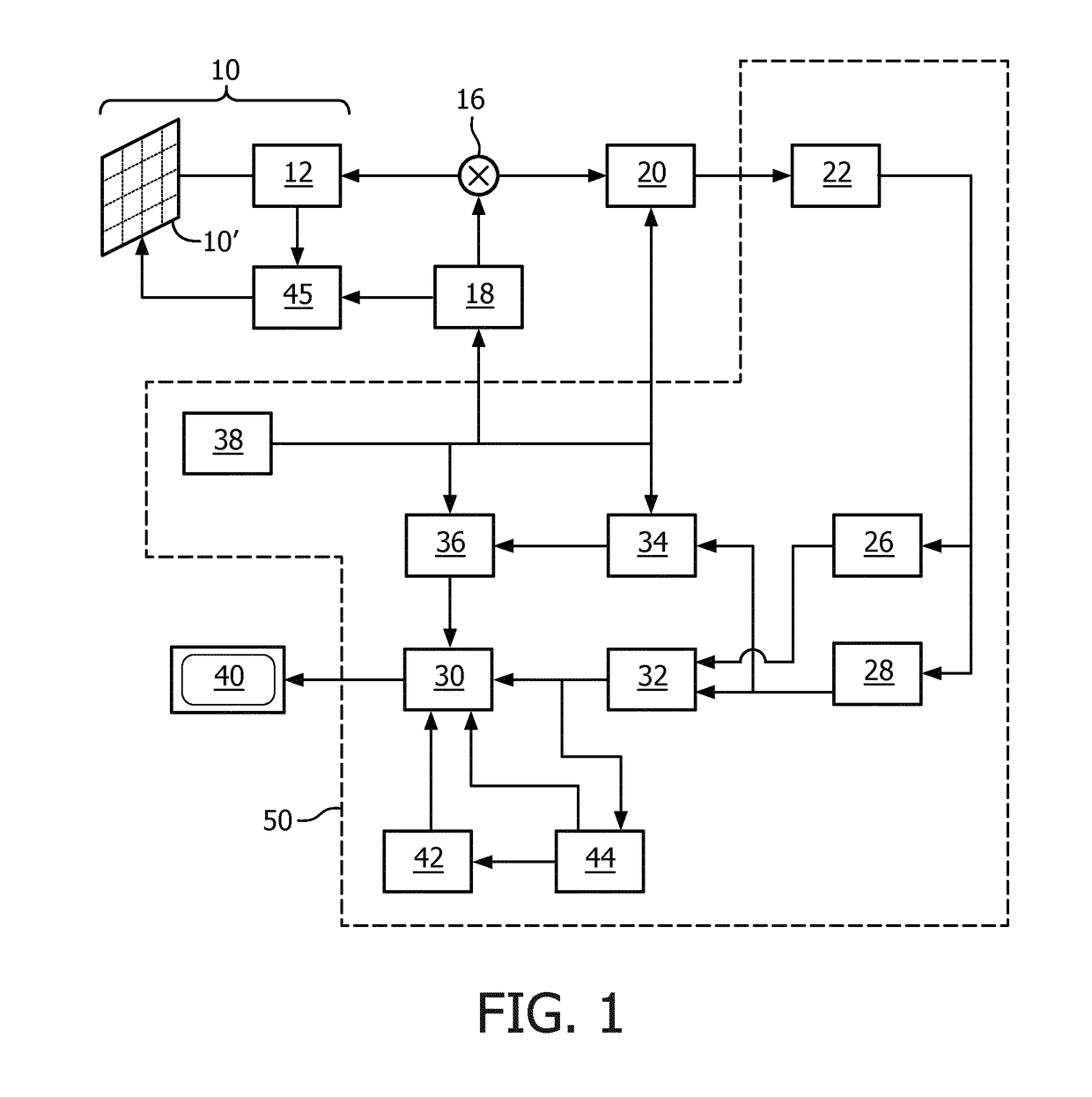
[0050]The general operation of an ultrasonic diagnostic imaging system will first be described, with reference to FIG. 1.

[0051]Note that the reception function of the system is in particular described below since this invention relates to the analog to digital conversion in the receive channel.

[0052]The system comprises an ultrasound probe 10 which has C...


PUM


Abstract

An ultrasound imaging system probe comprises an imaging transducer head and a reception circuit for processing received reflected ultrasound signals. The reception circuit comprises an analogue to digital sigma delta converter which comprises a closed loop which comprises a tunable band pass filter. This enables the analog to digital converter to process only the desired frequency band. The ADC conversion bandwidth and ENOB are in this way programmable giving a more efficient probe design, and also enabling analog to digital conversion early in the signal processing chain.

Description

FIELD OF THE INVENTION[0001]This invention relates to an ultrasound imaging system probe and the whole system, and an imaging method. It relates in particular to the analogue to digital converter circuits used in such imaging applications.BACKGROUND OF THE INVENTION[0002]Harmonic ultrasound imaging is one particular type of ultrasound imaging technique which is gaining increased interest. It exploits non-linear propagation of ultrasound through the body tissues. The high pressure portion of the wave travels faster than low pressure portions resulting in distortion of the shape of the wave. This change in waveform leads to generation of harmonics (multiples of the fundamental or transmitted frequency) from the tissue. For example, it is known to use the second harmonic to produce the image as the subsequent harmonics are of decreasing amplitude and hence insufficient to generate a proper image.[0003]The harmonic waves that are generated within the tissue increase with depth to a poin...

Claims


Application Information

Patent Timeline
Patent Type & Authority Applications(United States)
IPC IPC(8): G01S7/52A61B8/08A61B8/06G01S15/89
CPCG01S7/52046A61B8/488A61B8/065A61B8/5207G01S7/52077G01S7/52092G01S15/8925A61B8/42A61B8/48G01S15/8993G01S7/52025G01S7/52038G01S15/8915G01S7/5208H03M3/458A61B8/08G01S7/00
Inventor OUZOUNOV, SOTIR FILIPOV
Owner KONINKLJIJKE PHILIPS NV
Learn More