Attenuation map reconstruction from tof pet data

a technology of attenuation map and tof data, applied in tomography, applications, instruments, etc., can solve the problems of cross-talk artifacts, large artifacts, and inability to accurately and accurately determine or estimate the effect of accuracy and stably

Active Publication Date: 2018-12-13
RENESSELAER POLYTECHNIC INST
View PDF0 Cites 12 Cited by
  • Summary
  • Abstract
  • Description
  • Claims
  • Application Information

AI Technical Summary

Benefits of technology

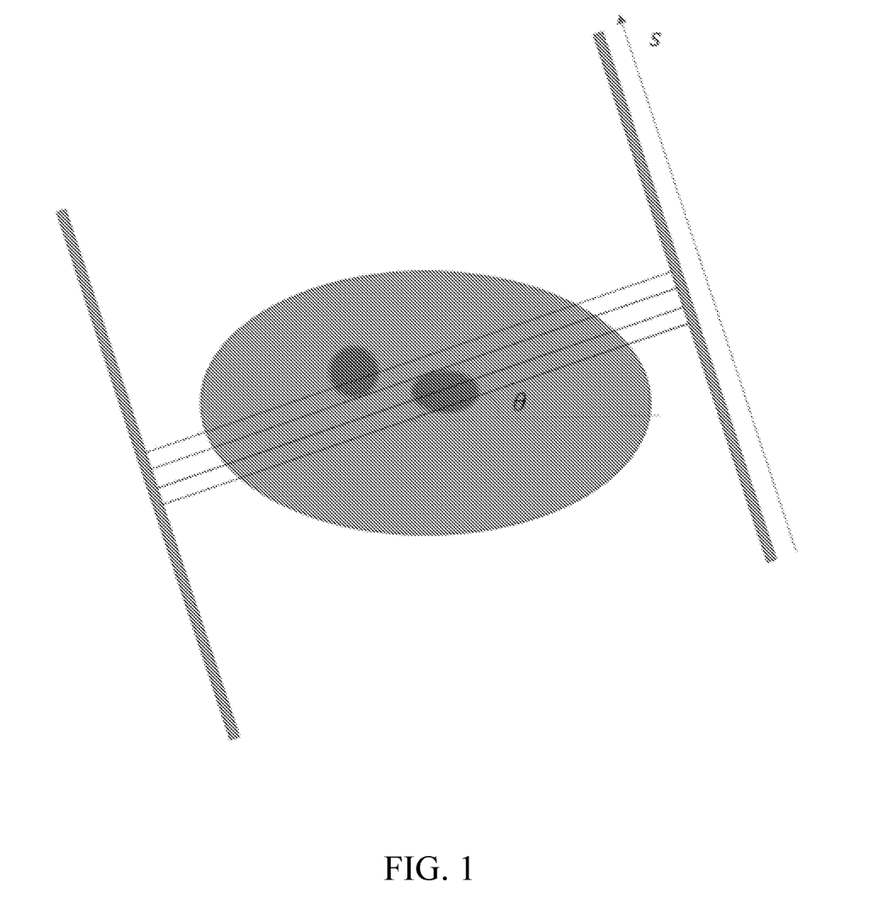
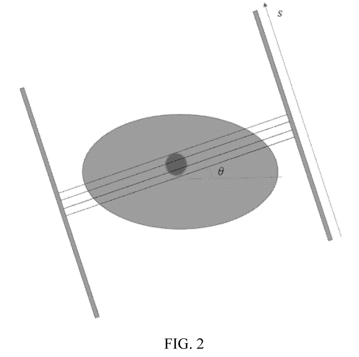
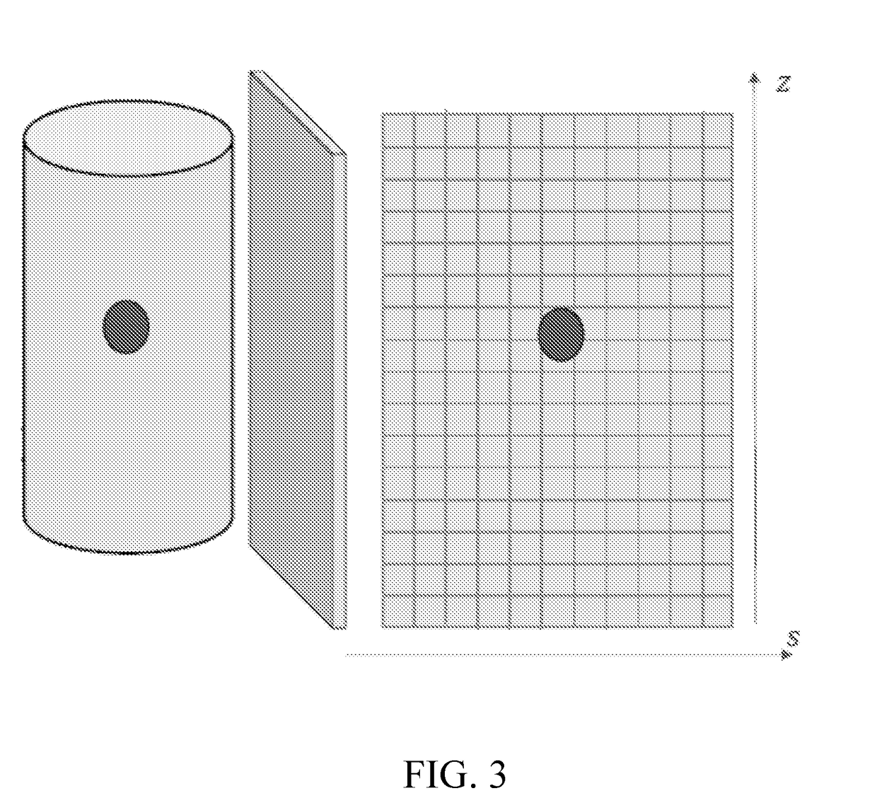
[0005]Embodiments of the subject invention provide novel and advantageous systems and methods for determining or estimating an attenuation sinogram and / or attenuation correction map for a time-of-flight (TOF) positron emission tomography (PET) scan using only TOF PET data, and including use of the total amount of tracer provided to the subject of the TOF PET scan. The total amount of provided (e.g., injected) tracer can be used to determine the otherwise unknown constant shift present when an attenuation sinogram is estimated using the gradient (e.g., derivative(s)) of the attenuation sinogram. In this way, the attenuation sinogram, and therefore the attenuation correction map for the TOF PET scan, can be accurately and stably determined or estimated without any additional knowledge on the attenuation sinogram or map.

Problems solved by technology

A PET image reconstructed with an incorrect attenuation map or with no attenuation map would suffer from significant artifacts.
However, there are significant mismatches between a CT image at an average energy of 60-80 kilo-electron-Volts (keV) and a PET attenuation background at 511 keV, and their physical features are quite different, which can cause substantial artifacts.
However, all of these techniques suffer from cross-talk artifacts.

Method used


Image

  • Attenuation map reconstruction from tof pet data
  • Attenuation map reconstruction from tof pet data
  • Attenuation map reconstruction from tof pet data

Examples


embodiment 1

[0045]A system for performing a time-of-flight (TOF) positron emission tomography (PET) scan, the system comprising:

[0046]a PET scanner configured to perform TOF PET scanning;

[0047]at least one processor; and

[0048]a machine-readable medium, in operable communication with the PET scanner and the at least one processor, having machine-executable instructions stored thereon that, when executed by the at least one processor, perform a method, the method comprising:[0049]obtaining an initial estimated attenuation singoram of a TOF PET scan, of the PET scanner, that has an unknown constant shift;[0050]determining the constant shift of the initial estimated attenuation singoram using the total amount of tracer provided (e.g., injected) to the subject (e.g., a human or animal patient) of the TOF PET scan, wherein determining the constant shift is done without using any further information other than TOF PET scan data; and[0051]determining (or estimating) the attenuation sinogram for the TOF...

embodiment 2

[0052]The system according to embodiment 1, wherein the method executed by the at least one processor further comprises:

[0053]reconstructing the TOF PET image using the attenuation sinogram and TOF PET data from the TOF PET scan.

embodiment 3

[0054]The system according to embodiment 2, wherein the method executed by the at least one processor further comprises:

[0055]performing pre-processing of the TOF PET data, before reconstructing the TOF PET image, to correct for random coincidences, estimate and subtract scattered photons, correct for detector dead-time, and / or correct for detector sensitivity.


PUM


Abstract

Systems and methods for determining an attenuation sinogram for a time-of-flight (TOF) positron emission tomography (PET) scan using only TOF PET data, and including use of the total amount of tracer provided to the subject of the TOF PET scan, are provided. The total amount of injected tracer can be used to determine the otherwise unknown constant shift present when an attenuation sinogram is estimated using the gradient of the attenuation sinogram. The attenuation sinogram can therefore be accurately and stably determined without any additional knowledge on the attenuation sinogram or map.

Description

CROSS-REFERENCE TO RELATED APPLICATION[0001]This application claims the benefit of U.S. Provisional Application Ser. No. 62 / 170,893, filed Jun. 4, 2015, which is incorporated herein by reference in its entirety, including any figures, tables, and drawings.BACKGROUND OF INVENTION[0002]In quantitative positron emission tomography (PET) imaging, the attenuation background (i.e., map) of the subject (e.g., a human patient or an animal) must be obtained or estimated to accurately reconstruct the radioactive tracer distribution. A PET image reconstructed with an incorrect attenuation map or with no attenuation map would suffer from significant artifacts. Existing methods for estimating the attenuation map of a PET image can be categorized into two general classes: transmission and non-transmission.[0003]Transmission methods are based on transmission data acquired with an external radionuclide source, computed tomography (CT), or magnetic resonance imaging (MRI) scan. In a PET / CT system, a...

Claims


Application Information

Patent Timeline
Patent Type & Authority Applications(United States)
IPC IPC(8): A61B6/00A61B6/03G06T11/00G21H5/02
CPCA61B6/5205A61B6/037G06T11/005G21H5/02A61B6/481A61B6/5258G06T11/003
Inventor WANG, GEYANG, QINGSONGCONG, WENXIANG
Owner RENESSELAER POLYTECHNIC INST
Why Eureka
Try Eureka