
Sail boat propulsion and stabilisation system and device

Inactive Publication Date: 2018-12-13
CHAVES MANOEL FRANCISCO CORTES
View PDF0 Cites 9 Cited by
  • Summary
  • Abstract
  • Description
  • Claims
  • Application Information

AI Technical Summary

Benefits of technology

This patent introduces a new system and device for propelling and stabilizing a sailboat that improves speed performance, comfort, and maneuverability. It reduces displacement and fuel consumption, and when powered by an engine, it generates even more stability and comfort. The integrated installation is simple, and the control panel is easily accessed through a tablet or smartphone. The device can be quickly lowered and lifted, and it contributes to the efficiency of the navigation.

Problems solved by technology

Over the centuries, the sail navigation has always been faced with stability problems due to the generation of more ballast and low weight (in the bottom or at the keel) in order to support strains of the sailing plan thereof.
This weight provides the hull with a higher hydrodynamic resistance that reduces the efficiency of the system;
When sailing under a weak wind, all that weight added to the keel sinks the hull even more, generates a larger wet surface in the live works and is good for nothing, since the weak wind does not heel over the boat.
Deep keels have a large wet surface (requiring internal volume to fill same with ballast), thus generating friction and reducing the speed even more;
The hull also sinks with the weight of the keel on its bulge, thus extending the wet surface and holding the boat, thus reducing its performance;
When the boat starts to heel over, the hydrodynamic profile of the conventional keel starts to work outside the perpendicular of the water line plan, thus substantially reducing its side sustentation efficiency, so that the boat stalls in the wind and generates vortices in the water, which vortices dissipate the power, thus reducing the boat speed;
When the boat approaches a port, cove or marina, the depth of the keel makes it difficult to dock because the draught of the boat is extended to three or more times the draught of the hull.
Thus, many ports cannot be accessed, and the commanders cannot seek shelter under adverse climatic conditions because they cannot approach such ports;
Another problem of the conventional keel is that its hydrodynamic profile is symmetrical to the center line.
In the fixed keel and center helm system, when the boat heels over, the vector center of all aerodynamic forces of the sails that promote the propulsion of the hull (sum of all forces that push the sailboat ahead) and the center of hydrodynamic resistance of the hull (sum of all the forces that hold the sailboat so that it does not increase its speed), are well unbalanced in relation to the boat center line.
On the other hand, the hydrodynamic resistance center of the hull is unbalanced windward due to the inclination of the hull and the large resistance of the keel.
When the boat is heeled over by the wind, the helm must be used all the time and, since its axis is not perpendicular to the water line plan, the performance of the helm is awfully bad, thus decreasing the speed of the boat.
This type of sailboat still has some inconveniences as compared to those reported in the previous case.
This type of sailboat also has some inconveniences shown in the designs above.
The task of changing the fluid of a board with another fluid can be delayed, thus complicating the application of the system;
The tank bulkheads, even when are not being used as the ballast, have their own weight, thus hindering the displacement of the boat.
More weight is almost always not a good measure.
Technical faults in the tilting mechanism of said keels bring about a higher cost for installing same, and also broken devices have generated and continue to generate serious accidents when navigating in the open sea;
Currently this system is known as the fastest and efficient available in the market for one-hull boats, but unfortunately the cost for acquiring and installing same is high; and
Another complex matter is the (excessively high) draught of said boats, as well as the need to place same in huge cradles when they are taken out of the water.
When the boat is in the port, its draught is huge.
A high draught is a serious problem, since small ports and marinas are faced with environment issues and huge dragging cost when the depths thereof are increased;
Said rebounding, pivoting or tilting keels have a wet surface and drag resistance, but they do not cooperate to laterally sustain the boat for supporting the side pressure of the sail plan, and therefore bowline keels to be handled by the crew need to be installed ahead of the mast bowline;
The system for pivoting or tilting system the keel is too expensive and requires strength no matter how hard the engineers work.
Briefly, the result is too much weight, a moving dead load, a high draught, and bowline keels that need to be lowered and lifted.
However, this type of sailboat still presents some inconveniences such as:
The DSS system does not provide any sustentation to compensate the sail plan pressures.
The draught of the boat is still very large, thus complicating the access to marinas as well as to park the boat out of water;
Another serious problem in the DSS is that it is not possible to change the angle of attack of the profile.
The DSS wing profile, by virtue of a problem in the concept of the design, because it is not deep (it cannot be deeper, since it does not allow to arrange the installation on the bulge of boat hulls) sometimes it arises partly or wholly in the surface, thus causing waves and turbulence that reduce the speed of the boat as well as diminish the sustentation of the wing;
Briefly, its installation occupies a lot of inner space in the boat, and is difficult to be installed in the already existing boats;
Although it has been named as a dynamic stability system, it is useless when one navigates in widely spread winds or stern winds;
Due to the fact that the wing is flush with the surface (close to the surface) there is a problem of cavitation on the back thereof.
When low immersed, the cavitation is difficult to control;
Similarly, when the boat has the sails fourled and is powered by the engine, there is no improvement in the stability and the rocking is not attenuated, thus causing discomfort to the passengers and members of the crew.

Method used


Image

  • Sail boat propulsion and stabilisation system and device
  • Sail boat propulsion and stabilisation system and device
  • Sail boat propulsion and stabilisation system and device

Examples


Embodiment Construction

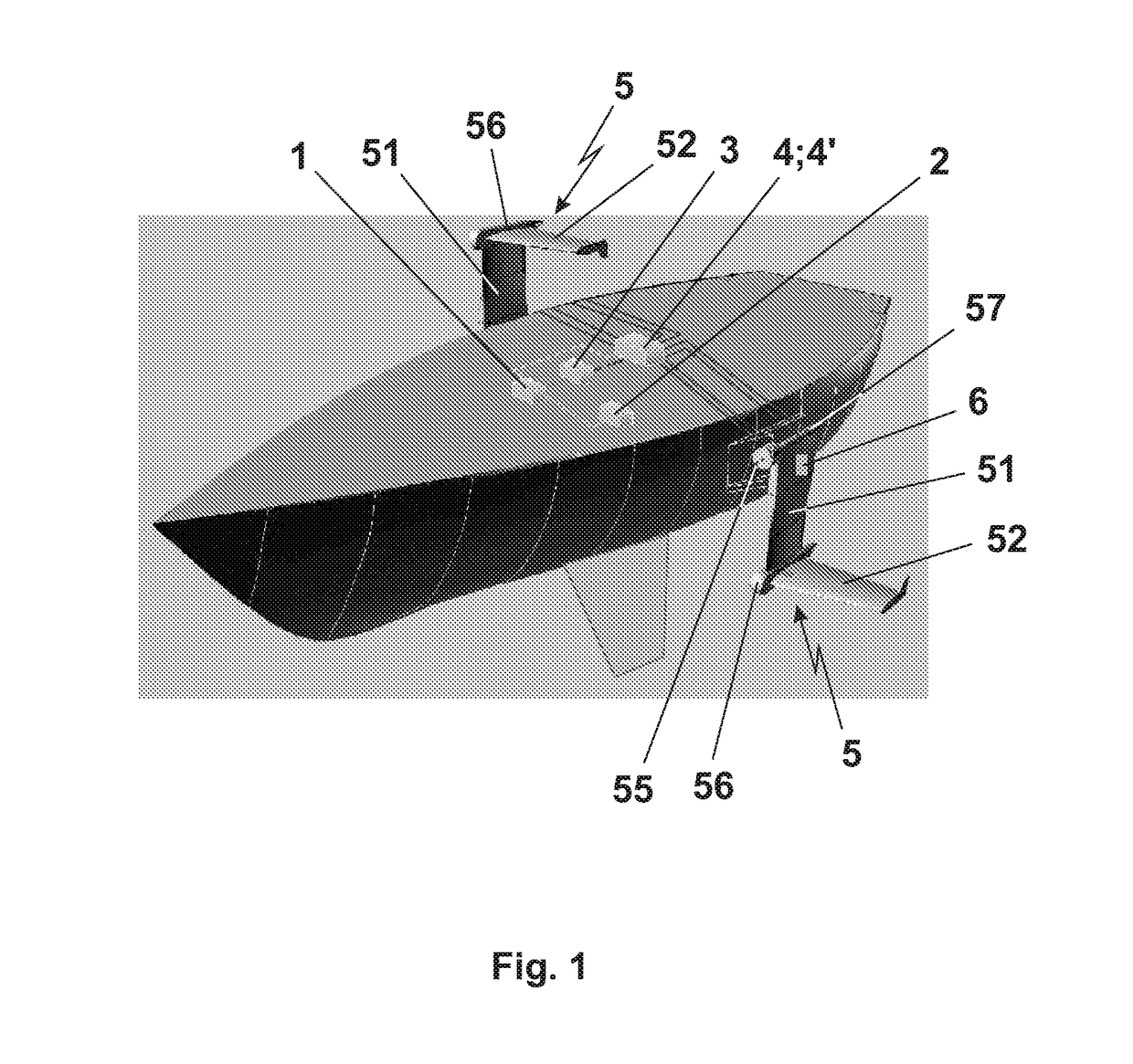
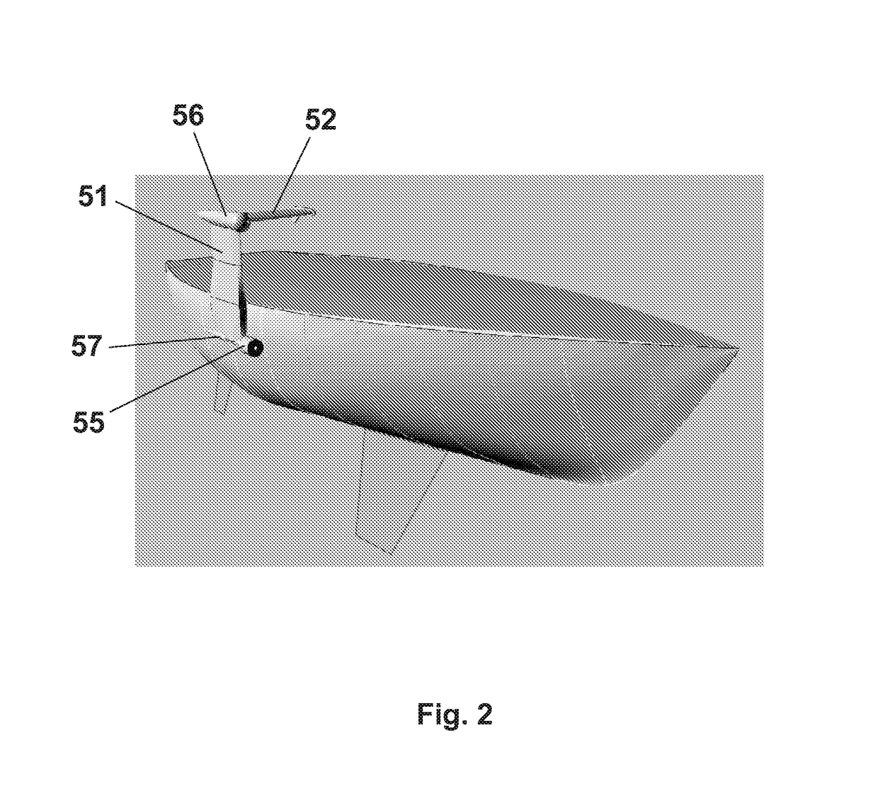
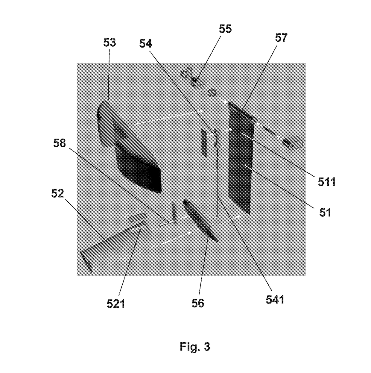
[0092]In accordance with FIGS. 1 and 2, the system comprises a control panel (1), actuated by a battery (2), connected to a hydraulic aggregate (3) that is connected to directional valves (4) and solenoids (4′) through which the device (5) for propelling and stabilizing a sailboat is actuated, said aggregate being provided with a wing keel (51), a counterbalance or “lift” wing (52) joined by a bulb (56), a cylindrical actuator (54) for the counterbalance lift wing (52), a hydraulic rotary actuator (55) for hoisting the assembly, a pivoting shaft (58) for the counterbalance wing (52) and a tilting shaft (57) for the assembly, which is coupled to the broadside or to the mounting base (53) provided for already existing boats, besides sensors of the angle of attack of the counterbalance or “lift” wing (52).

[0093]There are two options for the control panel (1) with regard to its electro-electronic sophistication: Standard or electronic stabilization, wherein:[0094]1. Standard option: in ...


PUM


Abstract

A sail boat propulsion and stabilisation system. The system uses a device to substantially increase the performance of sail or motor boats by reducing the displacement to increase speed and comfort during sailing, due to its light weight and dynamics. The system comprises a control panel connected to a hydraulic group which actuates the device. The device is provided with a keel wing and a counterbalance or lift wing joined by a bulb, a cylindrical actuator for the counterbalance and lift wing, a hydraulic rotary actuator for hoisting the assembly, an articulation shaft, and a tilting shaft for the assembly which is coupled to the broadside or to the mounting base beside sensors of the angle of attack of the counterbalance wing. The hydraulic group and the cylindrical hydraulic actuator are optionally replaced by a cylindrical electric actuator connected to the control panel and acting upon the counterbalance wing.

Description

[0001]The present patent application refers to a sail boat propulsion and stabilisation system that belongs to the nautical sector, and refers particularly to a system which, by means of a device developed for this end, extends substantially the performance of one-hull and multi-hull boats, and shall be used for increasing the final speed of the existing and to be designed sailboats, thus making it possible for the boat to reduce its light and dynamic displacement, therefore increasing the speed and comfort when sailing.STATE OF THE ART[0002]Over the centuries, the sail navigation has always been faced with stability problems due to the generation of more ballast and low weight (in the bottom or at the keel) in order to support strains of the sailing plan thereof.[0003]Over the years, sailboats have evolved to deeper keels and weights with hydrodynamic bodies in the form of bulbs. In parallel, salty water ballast tanks and fresh water ballast tanks have also been used, and more rece...

Claims


Application Information

Patent Timeline
IPC IPC(8): B63B39/06B63B1/24B63B1/30
CPCB63B39/062B63B1/242B63B1/246B63B1/30B63B39/06B63B2039/065B63B41/00B63B2035/009B63B39/02B63B43/04B63B43/08B63H9/04
Inventor CHAVES, MANOEL FRANCISCO CORTES
Owner CHAVES MANOEL FRANCISCO CORTES
Learn More