
Solar cell and method of manufacturing the same

Active Publication Date: 2018-12-13
JUSUNG ENG
View PDF4 Cites 0 Cited by
  • Summary
  • Abstract
  • Description
  • Claims
  • Application Information

AI Technical Summary

Benefits of technology

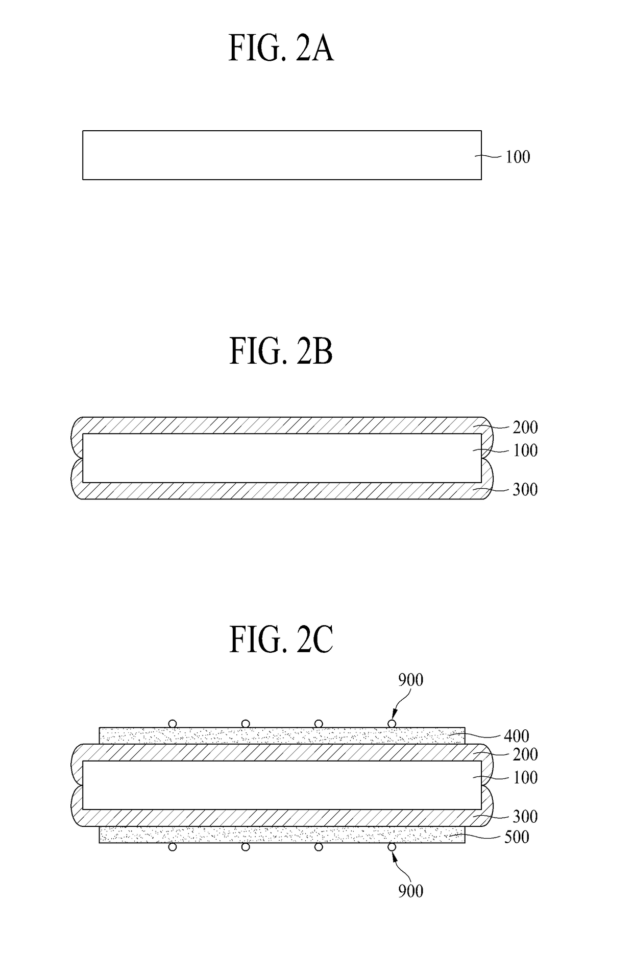
The present invention relates to a method of preventing short circuits in semiconductor wafers by removing particles from the surface of the wafer. By performing plasma treatment on the surface of the conductive layers, a connection between the semiconductor layers is cut off, reducing the risk of short circuits. This also improves the transmittance of sunlight and the flow of electric current.

Problems solved by technology

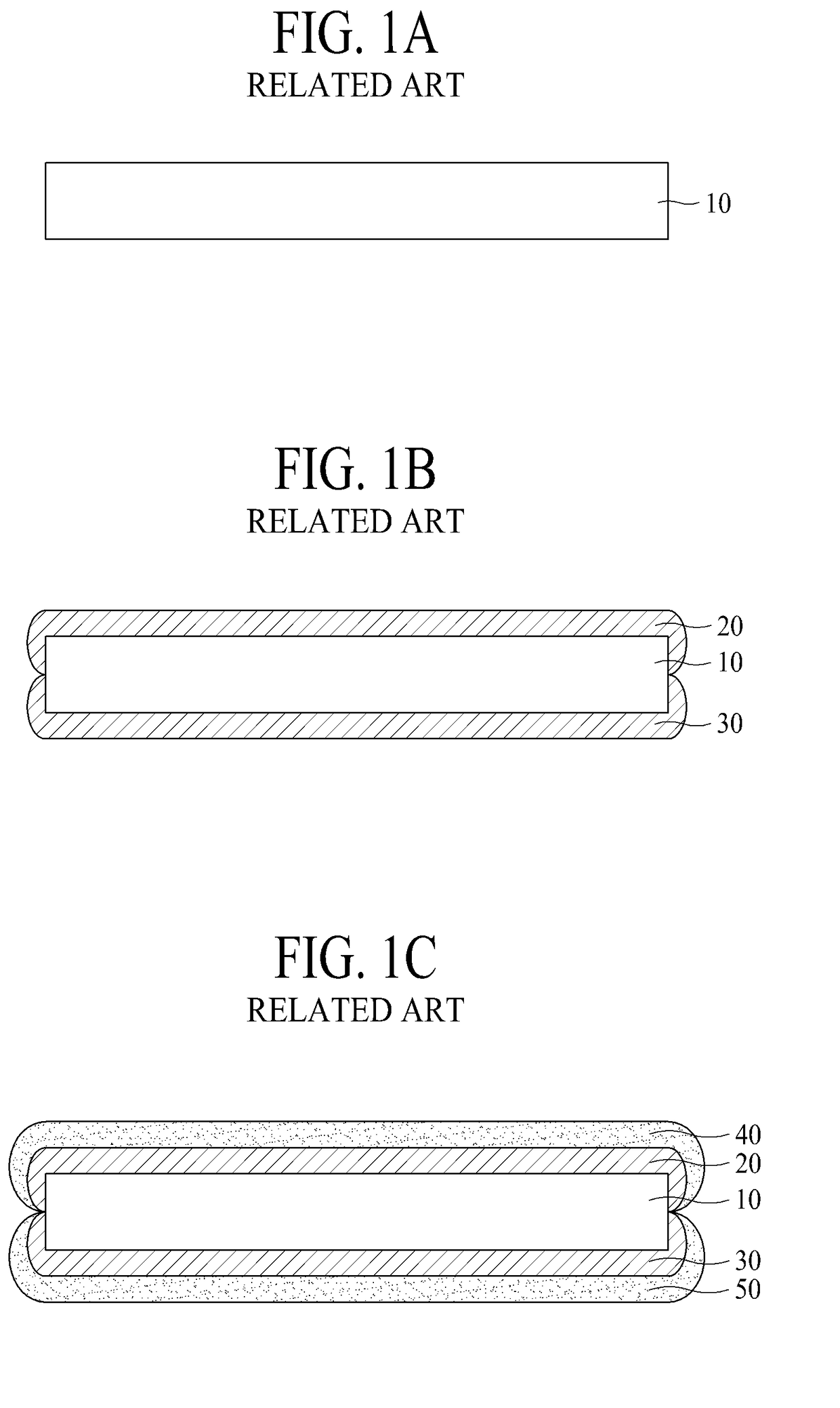
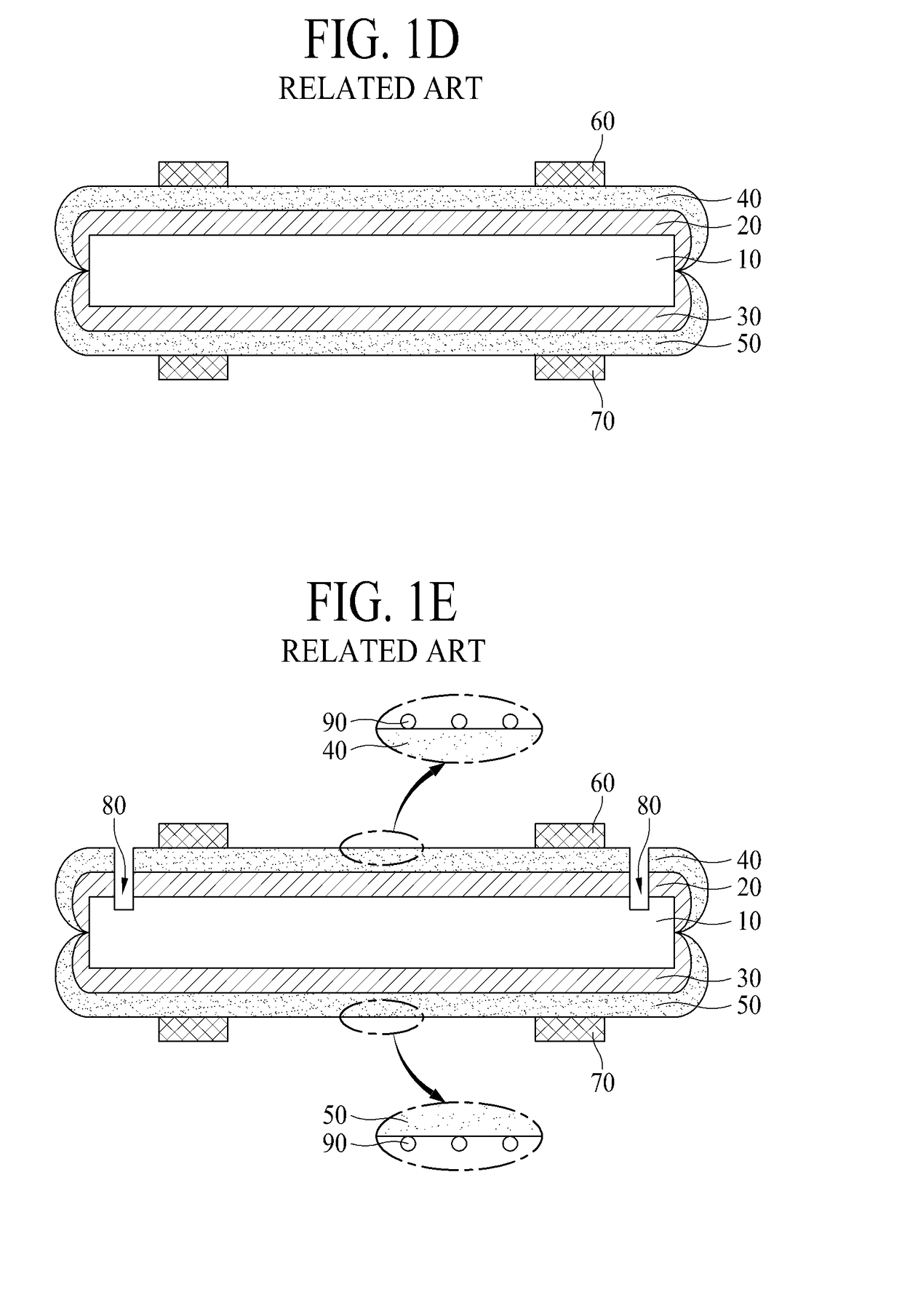
First, in the related art, the separation part 80 is formed for preventing short circuit in the above-described process of FIG. 1E, and in this case, a carrier such as a hole or an electron is trapped in the separation part 80 area, causing a problem where an efficiency of the solar cell is reduced.
As described above, if the particles 90 are located on the upper surface of the first transparent conductive layer 40 and the lower surface of the second transparent conductive layer 50, a transmittance of sunlight is reduced by the particles 90, and moreover, a flow of a current is hindered by the particles 90, causing a problem where an efficiency of the solar cell is reduced.

Method used


Image

  • Solar cell and method of manufacturing the same
  • Solar cell and method of manufacturing the same
  • Solar cell and method of manufacturing the same

Examples


Embodiment Construction

[0037]Advantages and features of the present invention, and implementation methods thereof will be clarified through following embodiments described with reference to the accompanying drawings. The present invention may, however, be embodied in different forms and should not be construed as limited to the embodiments set forth herein. Rather, these embodiments are provided so that this disclosure will be thorough and complete, and will fully convey the scope of the present invention to those skilled in the art. Further, the present invention is only defined by scopes of claims.

[0038]A shape, a size, a ratio, an angle, and a number disclosed in the drawings for describing embodiments of the present invention are merely an example, and thus, the present invention is not limited to the illustrated details. Like reference numerals refer to like elements throughout. In the following description, when the detailed description of the relevant known function or configuration is determined t...


PUM


Abstract

The present invention provides a method of manufacturing a solar cell, the method including: a process of forming a first semiconductor layer on an upper surface of a semiconductor wafer and forming a second semiconductor layer, having a polarity different from a polarity of the first semiconductor layer, on a lower surface of the semiconductor wafer; a process of forming a first transparent conductive layer on an upper surface of the first semiconductor layer to externally expose a portion of the first semiconductor layer and forming a second transparent conductive layer on a lower surface of the second semiconductor layer to externally expose a portion of the second semiconductor layer; and a plasma treatment process on at least one of the first transparent conductive layer and the second transparent conductive layer, wherein the plasma treatment process includes a process of removing the externally exposed portion of the first semiconductor layer and the externally exposed portion of the second semiconductor layer.

Description

TECHNICAL FIELD[0001]The present invention relates to a solar cell, and more particularly, to a solar cell based on a combination of a wafer type solar cell and a thin film type solar cell.BACKGROUND ART[0002]Solar cells are devices that convert light energy into electrical energy, based on a characteristic of a semiconductor.[0003]The solar cells have a PN junction structure where a positive (P)-type semiconductor and a negative (N)-type semiconductor are joined to each other. When sunlight is incident on a solar cell having the PN junction structure, a hole and an electron are generated in the semiconductors by energy of the incident sunlight. At this time, due to an electric field which is generated in a PN junction, the hole (+) moves to the P-type semiconductor, and the electron (-) moves to the N-type semiconductor, thereby generating an electric potential to produce power.[0004]The solar cells may be categorized into wafer type solar cells and thin film type solar cells.[0005...

Claims


Application Information

Patent Timeline
IPC IPC(8): H01L31/20H01L31/18H01L31/0747
CPCH01L31/208H01L31/1884H01L31/202H01L31/0747H01L31/1804H01L31/186H01L31/1888Y02E10/52Y02E10/547Y02E10/548Y02P70/50H01L31/022425H01L31/022466H01L31/02366H01L31/04H01L31/18H01L31/0445Y02E10/50H01L21/0234H01L21/268H01L21/3065H01L21/32136H01L21/76826H01L31/022433H01L31/022483H01L31/0236H01L31/035281H01L31/06H01L31/068H01L31/072H01L31/075H01L31/20H01L31/056
Inventor SEO, JEONG HOKWON, SOON BUMKIM, KI-DUCKKIM, JONG INPARK, CHANG KYUNSHIN, WON SUKLIM, KYOUNG JINJIN, BEOP JONG
Owner JUSUNG ENG
Learn More