Soldering method and soldering structure

Active Publication Date: 2018-12-20
YAZAKI CORP
View PDF2 Cites 0 Cited by
  • Summary
  • Abstract
  • Description
  • Claims
  • Application Information

AI Technical Summary

Benefits of technology

[0008]According to the soldering method of the present invention, the damming structure formed at the periphery of the soldering portion keeps the flux, that is supplied with the solder, to the soldering portion during the soldering. Since the flux serves to remove the oxide film on the metal surface, by keeping the flux at the soldering portion as described above, the oxide film on the soldering portion can be removed with high removal efficiency. Consequently, even if the metallic terminal includes a thick oxide film to add the corrosion resistance, the oxide film at the soldering portion can be removed by the flux with high removal efficiency, thereby improving the wettability of the solder during the soldering. That is, according to the soldering method of the present invention, the soldering of the core wi

Problems solved by technology

Generally, such oxide film has low solder wettability, cau

Method used


Image

  • Soldering method and soldering structure
  • Soldering method and soldering structure
  • Soldering method and soldering structure

Examples


Example

[0023]The following will explain an exemplary embodiment of the present invention.

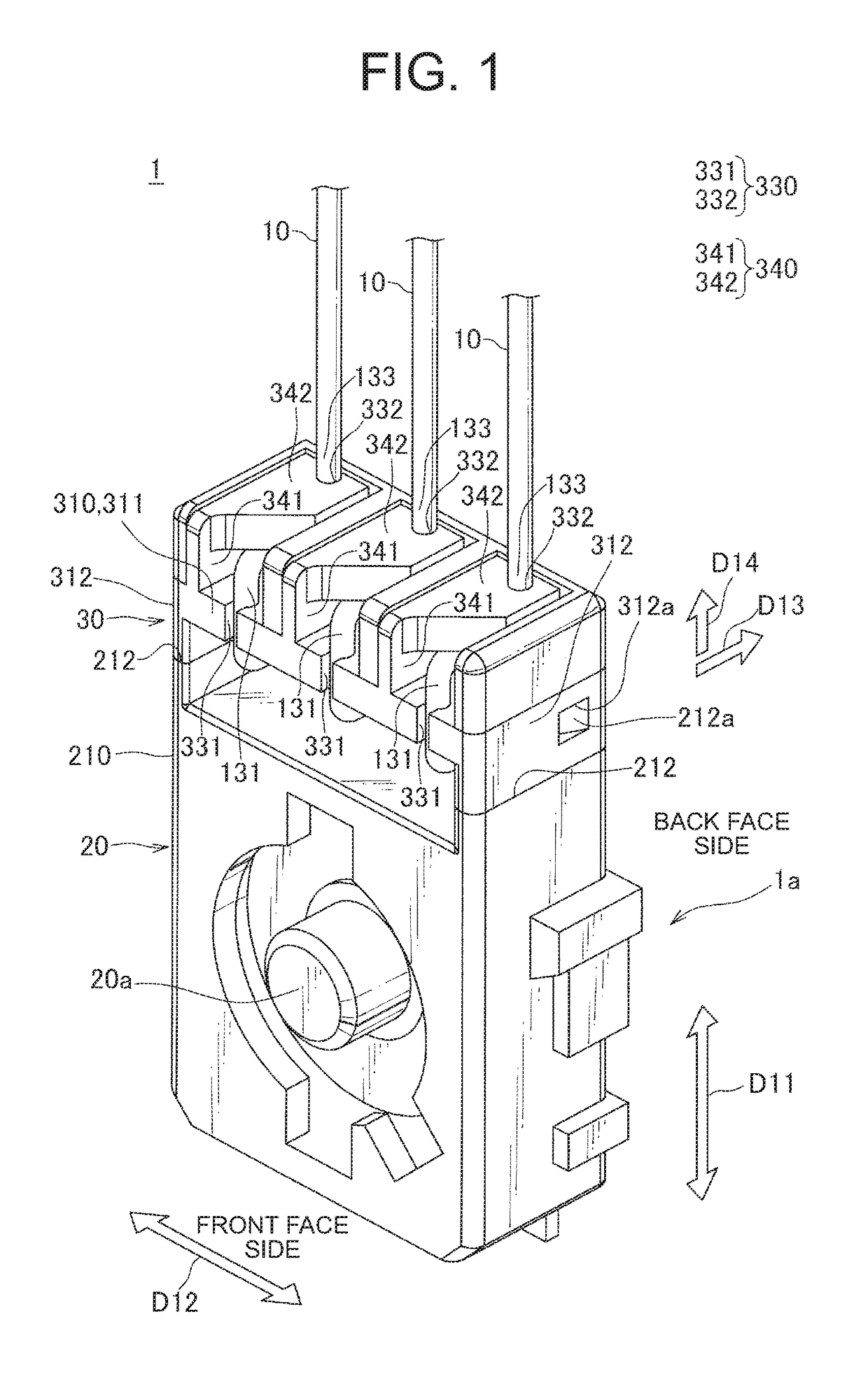
[0024]FIG. 1 is an illustration showing an example of an electrical device applied with one embodiment of the present invention. FIG. 1 shows a sensor device 1 of a fluid level sensor configured to detect a fluid level and such within a fuel tank of an automobile, for example. The fluid level sensor includes the sensor device 1, a float configured to move up and down along with a change in the fluid level, and a magnet movably attached with respect to the sensor device 1 and connected, via an arm, to the float. Herein, the sensor device 1 of the fluid level sensor is described as one example of an electrical device, and other components of the fluid level sensor including the float and the magnet are omitted in the drawings.

[0025]The sensor device 1 shown in FIG. 1 is configured to detect the movement of the magnet connected, via the arm, to the float which moves up and down along with the change in th...


PUM

PropertyMeasurementUnit
Widthaaaaaaaaaa
Areaaaaaaaaaaa

Abstract

Provided is a soldering method for soldering a tip end of an electric wire to a soldering portion of a metallic terminal which allows the soldering to be performed with excellent workability. The method includes a damming structure forming step forming a damming structure at a periphery of the soldering portion to dam a solder which is supplied in a molten state with a flux to the soldering portion to keep the solder at the soldering portion, an electric wire setting step setting the tip end of the electric wire at the soldering portion ready for soldering, and a solder supplying step supplying the solder in the molten state with the flux to the soldering portion to perform the soldering.

Description

CROSS REFERENCE TO RELATED APPLICATION[0001]The priority application Japanese Patent Application No. 2017-120306 upon which this patent application is based is hereby incorporated by reference.BACKGROUND OF THE INVENTIONField of the Invention[0002]The present disclosure relates to a soldering method and a soldering structure for soldering a tip end of an electric wire to a soldering portion of a metallic terminal.Description of the Related Art[0003]A variety of electrical devices having a metallic terminal to which an electric wire is to be soldered are conventionally known. An example of such electrical devices is shown in Japanese Patent Application Publication No. 2014-163880, which discloses a fluid level sensor for detecting a fluid level and such of a fuel within a fuel tank of an automobile, for example. This fluid level sensor detects a movement of a magnet connected, via an arm, to a float that moves up and down along with a change in a fluid level, and is provided with a b...

Claims


Application Information

Patent Timeline
IPC IPC(8): B23K1/20H01R43/02B23K1/00
CPCB23K1/20H01R43/0235B23K1/0016H01R4/024G01F23/38H01R4/027H01R4/028H01R43/02H01R43/0263H01R2201/20H01R13/5833B23K2101/38
Inventor KATO, AKIOKATO, SHINPEIKARUBE, HISASHI
Owner YAZAKI CORP
Why Eureka
Try Eureka