Porous structures produced by additive layer manufacturing

a technology of additive manufacturing and porous structures, which is applied in the direction of additive manufacturing processes, prostheses, manufacturing tools, etc., can solve the problems of inability to shape for a proper fit in a non-uniform space, loosening of the aseptic implant and cement, and lack of flexibility of the cement used to retain bone, so as to facilitate bone ingrowth and promote bone ingrowth

Active Publication Date: 2018-12-20
HOWMEDICA OSTEONICS CORP
View PDF0 Cites 41 Cited by
  • Summary
  • Abstract
  • Description
  • Claims
  • Application Information

AI Technical Summary

Benefits of technology

[0043]In accordance with another aspect, bone ingrowth may be facilitated. In facilitating such bone ingrowth, a porous tissue ingrowth structure may be formed in the shape of a mesh implant. In forming the mesh implant, a first layer of a material may be deposited onto a substrate. A first layer of the material may be scanned with a high energy beam to at least partially melt the first layer of the material. Successive layers of the material may be deposited onto the first layer. Each of the successive layers of the material may be scanned with the high energy beam at predetermined locations to form at least a first segment overlapping a second segment and underlapping a third segment. The mesh implant may be shaped into a desired shape. The mesh implant may have a porosity to promote bone ingrowth. The mesh implant may be placed against a bone portion. A bone implant may be placed against bone cement such that the bone cement contacts both the mesh implant and the bone implant. The mesh implant may prevent contact of the bone cement with bone ingrown into the mesh implant.

Problems solved by technology

Even proper preparation of delivery of bone cement to a smooth bony surface can result in aseptic loosening of the implant and cement over time, especially when filling large void spaces such as in the proximal tibia and distal femur, requiring a revision surgery to be performed.
Current implants, which typically require the use of biocompatible materials such as titanium, used to retain bone cement lack flexibility and are difficult to shape for a proper fit in a non-uniform space.
Such implants are non-porous and thus lack limited surface area for contact with bone.
Implants produced using ALM techniques have been built with strong scaffolds, but such implants are too rigid to allow for adequate deformation to fill void spaces created by bone degradation.
However, the use of such molds creates waste both in terms of physical waste as well as the time to prepare these prostheses.

Method used


Image

  • Porous structures produced by additive layer manufacturing
  • Porous structures produced by additive layer manufacturing
  • Porous structures produced by additive layer manufacturing

Examples


Embodiment Construction

[0097]This invention relates generally to generating computer models of three-dimensional structures. These models may be used to prepare porous tissue in-growth structures in medical implants and prostheses. The models may include features corresponding to tangible structures.

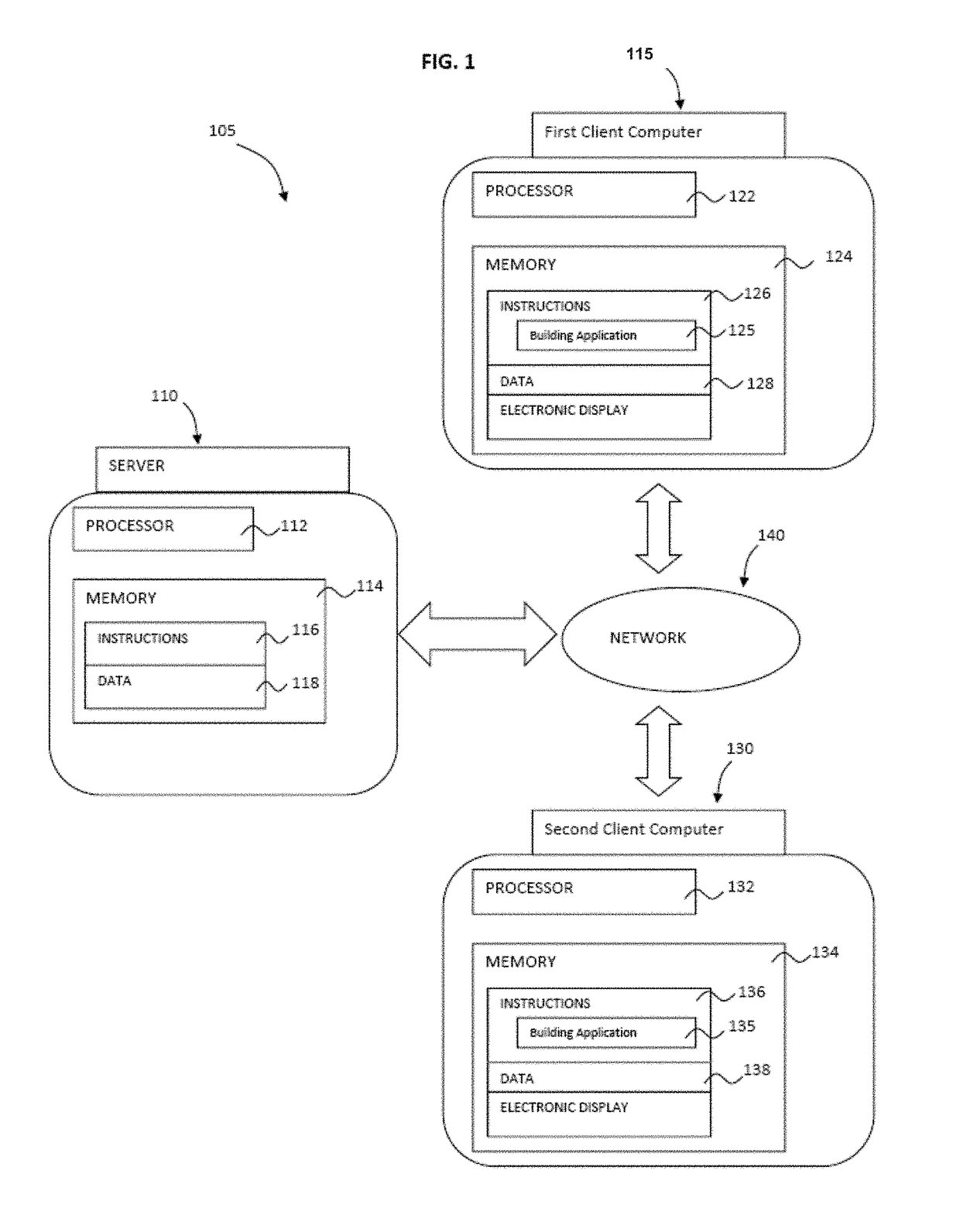
[0098]FIG. 1 depicts system 105 that may be used, among other functions, to generate, store and share three-dimensional models of structures. System 105 may include at least one server computer 110, first client computer 115, and in some instances, at least second client computer 130. These computers may send and receive information via network 140. For example, a first user may generate a model at first client device 115. The model may then be uploaded to server 110 and distributed via network 140 to second client computer 130 for viewing and modification by a second user, who or which may be the first user.

[0099]Network 140, and intervening communication points, may comprise various configurations and protoc...


PUM

PropertyMeasurementUnit
angleaaaaaaaaaa
diameteraaaaaaaaaa
diameteraaaaaaaaaa

Abstract

A three-dimensional structure is formed when layers of a material are deposited onto a substrate and scanned with a high energy beam to at least partially melt each layer of the material. Upon scanning the layers at predetermined locations a tube device having a first tube and a second tube intersected with the first tube is formed.

Description

CROSS-REFERENCE TO RELATED APPLICATION[0001]The present application claims the benefit of the filing date of U.S. Provisional Patent Application No. 62 / 520,221, filed Jun. 15, 2017, the disclosure of which is hereby incorporated herein by reference.FIELD OF THE INVENTION[0002]The present invention relates generally to preparing porous structures, and in particular to the preparation of mesh structures by way of additive manufacturing.BACKGROUND OF THE INVENTION[0003]The field of free-form fabrication has seen many important recent advances in the fabrication of articles directly from computer controlled databases. These advances, many of which are in the field of rapid manufacturing of articles such as prototype parts and mold dies, have greatly reduced the time and expense required to fabricate articles. This is in contrast to conventional machining processes in which a block of material, such as a metal, is machined according to engineering drawings.[0004]Examples of modern rapid ...

Claims


Application Information

Patent Timeline
Patent Type & Authority Applications(United States)
IPC IPC(8): B23K26/354B33Y10/00B33Y80/00B23K26/34
CPCB23K26/354B33Y10/00B33Y80/00B23K26/34A61F2/82A61F2002/30985A61F2240/001B29C64/386B29C64/10B22F3/1115B22F5/10C22C5/04B22F2999/00C22C14/00Y02P10/25B22F10/28B22F3/10B22F10/20
Inventor STAMP, ROBINROBINSON, JOSEPHWALSH, GEAROIDLAU, RACHEL KING-HA
Owner HOWMEDICA OSTEONICS CORP
Why Eureka
Try Eureka