Supercharge Your Innovation With Domain-Expert AI Agents!

Optical filter, ambient light sensor and sensor module

a sensor module and optical filter technology, applied in the direction of optical radiation measurement, instruments, using reradiation, etc., can solve the problems of reducing the detection accuracy of the ambient light sensor, the difficulty of accurately detecting the illumination and color tone, and the decrease of the visible light transmittance, etc., to achieve high visible light transmittance and near infrared cut performance, low dependence on the incident angle, and high accuracy

Active Publication Date: 2018-12-20
JSR CORPORATIOON
View PDF10 Cites 15 Cited by
  • Summary
  • Abstract
  • Description
  • Claims
  • Application Information

AI Technical Summary

Benefits of technology

The present invention provides an optical filter that can transmit visible light and reduce near infrared light, making it useful for ambient light sensor applications. The filter is suitable for both perpendicular and oblique incident light, resulting in accurate measurements of illuminance and color temperature. The sensor is less dependent on the angle at which light enters the system, resulting in more accurate and reliable data.

Problems solved by technology

On the other hand, according to demand for emphasis on design properties of information terminal devices, it is necessary to lower a transmittance of a transmission window through which light passes before it is incident on the ambient light sensor (to darken an external appearance), and there are problems that, when an incident amount of visible light with respect to infrared light decreases, it is difficult to accurately detect an illuminance and a color tone, and an erroneous operation may occur.
However, since optical characteristics of a near infrared cut filter in which a metal multilayer thin film is formed on a glass plate greatly change according to an incident angle of incident light, there is a problem of detection accuracy of the ambient light sensor decreasing.
However, in a near infrared cut filter, when an amount of near infrared absorbing particles added increases, there is a problem of a visible light transmittance decreasing.

Method used


Image

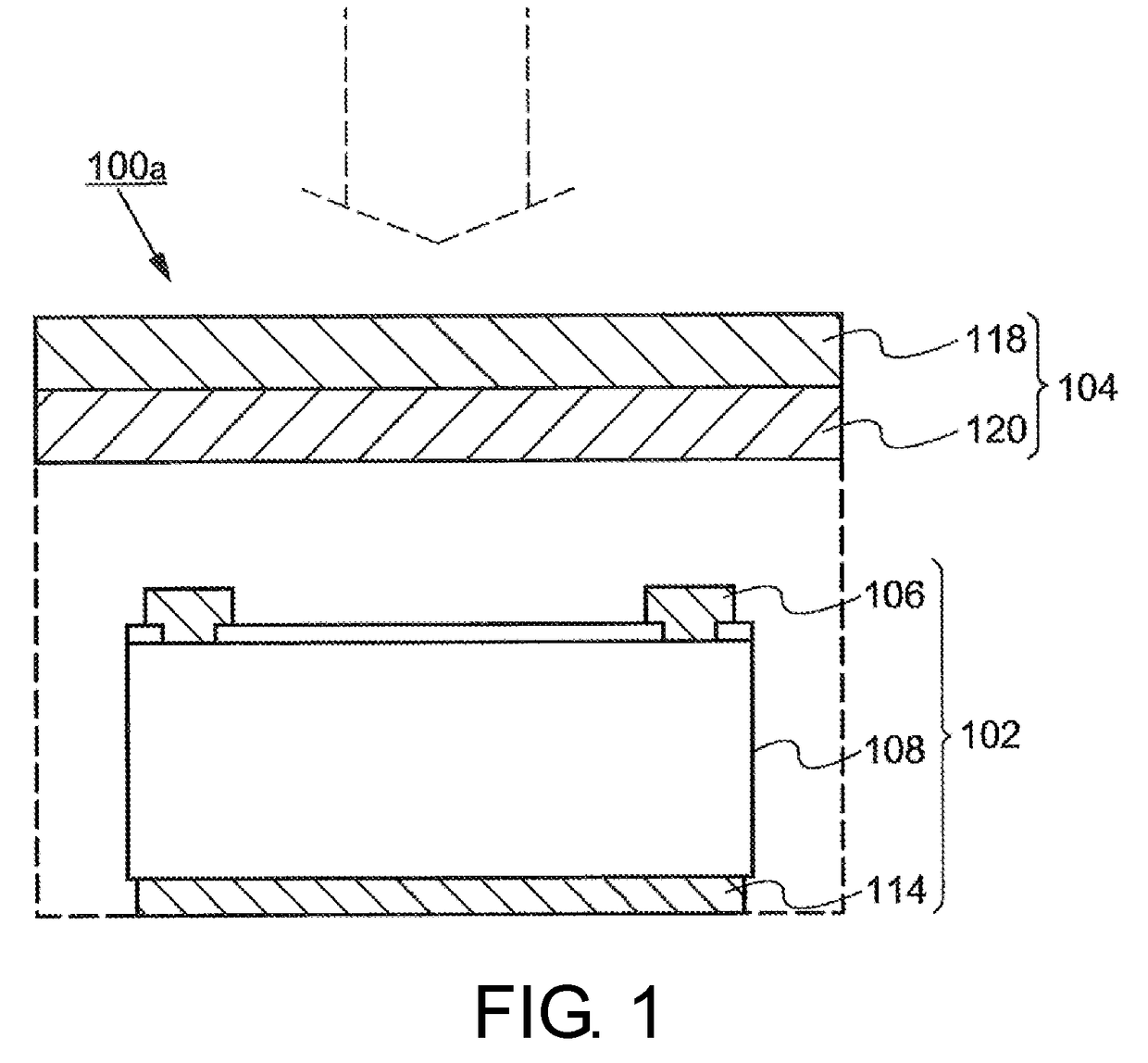
  • Optical filter, ambient light sensor and sensor module
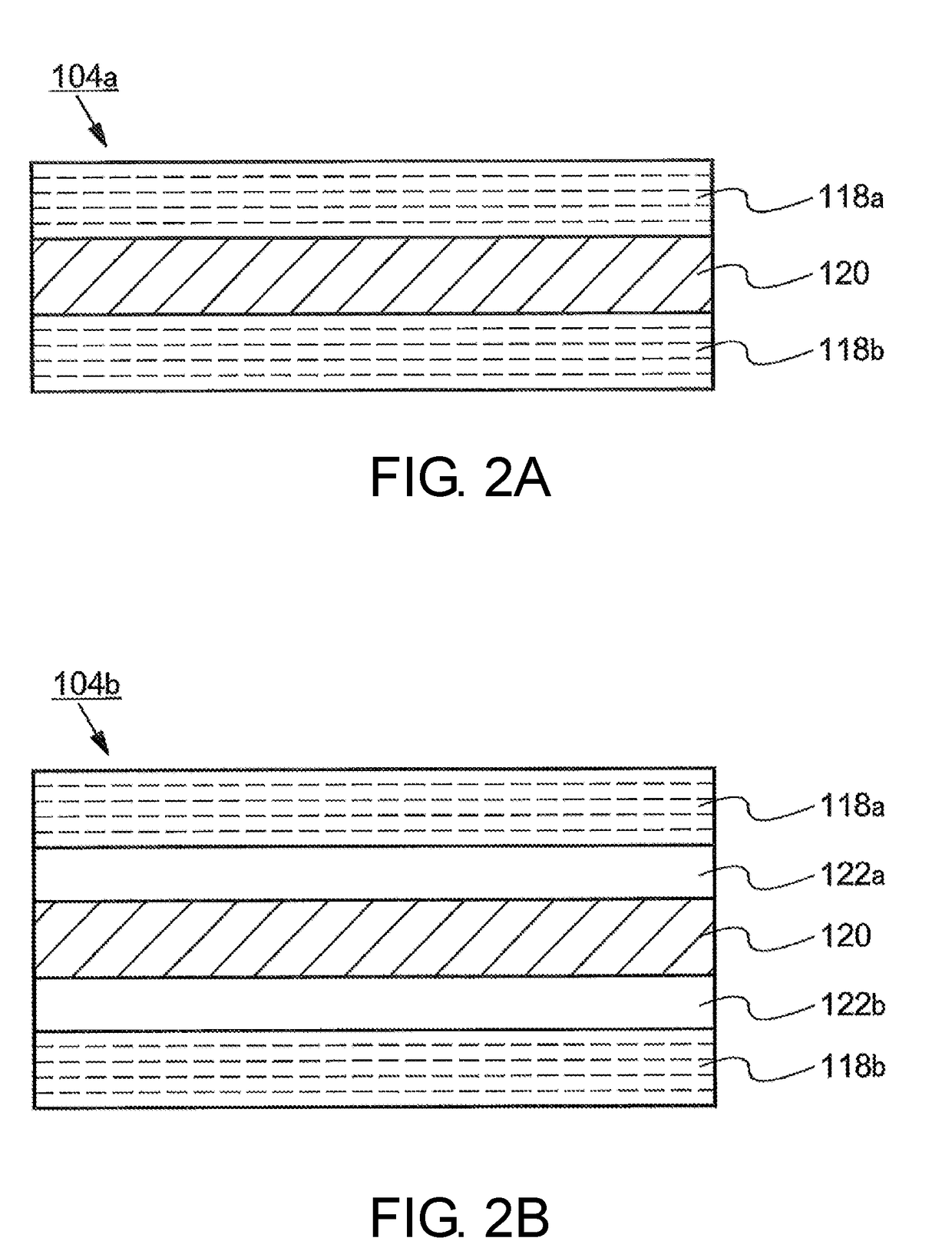
  • Optical filter, ambient light sensor and sensor module
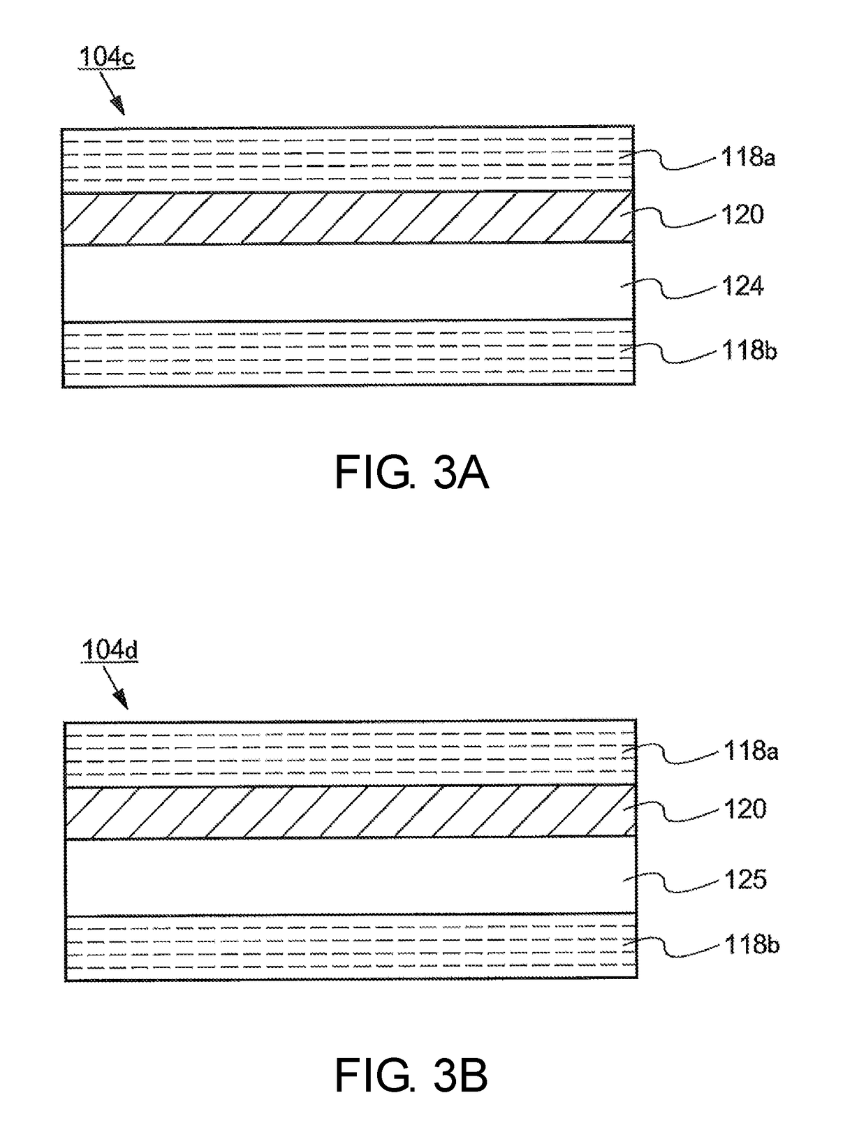
  • Optical filter, ambient light sensor and sensor module

Examples


examples

[0366]The present invention will be described below with reference to examples, but the present invention is not limited to the examples. Here, unless otherwise specified, “parts” and “%” refer to “parts by weight” and “weight %.” In addition, a method of measuring values of physical properties and a method of evaluating physical properties are as follows.

[0367]The molecular weight of a resin was measured by the following (a), (b) or (c) method in consideration of solubility of each resin in a solvent and the like.

[0368](a) A weight average molecular weight (Mw) and a number average molecular weight (Mn) in terms of polystyrene standards were measured using a gel permeation chromatography (GPC) device commercially available from WATERS (150C type, column: H type column commercially available from Tosoh Corporation, eluting solvent: o-dichlorobenzene).

[0369](b) A weight average molecular weight (Mw) and a number average molecular weight (Mn) in terms of polystyrene standards were mea...

synthesis examples

[0380]The compound (A) used in the following example and comparative examples was synthesized by a generally known method. As the general synthesis method, for example, methods described in Japanese Patent No. 3366697, Japanese Patent No. 2846091, Japanese Patent No. 2864475, Japanese Patent No. 3703869, Japanese Unexamined Patent Application Publication No. S60-228448, Japanese Unexamined Patent Application Publication No. H1-146846, Japanese Unexamined Patent Application Publication No. H1-228960, Japanese Patent No. 4081149, Japanese Unexamined Patent Application Publication No. S63-124054, “Phthalocyanine-Chemistry and Functions” (IPC, 1997), Japanese Unexamined Patent Application Publication No. 2007-169315, Japanese Unexamined Patent Application Publication No. 2009-108267, Japanese Unexamined Patent Application Publication No. 2010-241873, Japanese Patent No. 3699464, and Japanese Patent No. 4740631 can be exemplified.

synthesis example 1

Resin Synthesis Example 1

[0381]100 parts of 8-methyl-8-methoxycarbonyltetracyclo[4.4.0.12,5.17,10]dodeca-3-ene (hereinafter referred to as “DNM”) represented by the following Formula (2), 18 parts of 1-hexene (molecular weight regulator), and 300 parts of toluene (solvent for a ring-opening polymerization reaction) were put into a nitrogen-purged reaction container and this solution was heated at 80° C. Next, in the solution in the reaction container, 0.2 parts of a toluene solution of a triethylaluminum (0.6 mol / liter) as a polymerization catalyst and 0.9 parts of a toluene solution of a methanol-modified tungsten hexachloride (concentration 0.025 mol / liter) were added thereto, this solution was heated and stirred at 80° C. for 3 hours, and thus a ring-opening polymerization reaction was caused to obtain a ring-opening polymer solution. A polymerization conversion rate in the polymerization reaction was 97%.

[0382]1,000 parts of a ring-opening polymer solution obtained in this manne...


PUM

PropertyMeasurementUnit
wavelength rangeaaaaaaaaaa
ODaaaaaaaaaa

Abstract

One object of the present disclosure is to show an optical filter capable of realizing both an excellent visible light transmittance and an excellent near-infrared ray-shielding performance even if an incident angle becomes large. The optical filter of the present disclosure has a base material (i) including a light absorbing layer, and transmits visible light, wherein the light absorbing layer has a maximum absorption in a wavelength range of 750 nm to 1,150 nm, and in a wavelength range of 850 nm to 1,050 nm, an average OD value measured in a direction perpendicular to the optical filter is 2.0 or more, and an average OD value measured at an angle of 60° with respect to the direction perpendicular to the optical filter is 2.0 or more.

Description

TECHNICAL FIELD[0001]The present invention relates to an optical filter, an ambient light sensor and a sensor module, and particularly, to an optical filter containing a dye compound that has absorption in a specific wavelength range, an ambient light sensor using the optical filter, and a sensor module including the optical filter.BACKGROUND ART[0002]In recent years, the development of ambient light sensors that are applied to information terminal devices such as smartphones and tablet terminals has progressed. The ambient light sensors in the information terminal devices are used as an illuminance sensor configured to detect an illuminance of an environment in which the information terminal device is placed and dim the brightness of a display, and a color sensor configured to detect a color tone of an environment in which the information terminal device is placed and adjust a color tone of a display.[0003]In order to naturally match human vision sensitivity and a luminance and a c...

Claims


Application Information

Patent Timeline
Patent Type & Authority Applications(United States)
IPC IPC(8): G01J1/04G01J1/42G01S17/08G02B5/20G02B1/04G02B5/26
CPCG01J1/0488G01J1/4204G01S17/08G02B5/208G02B1/04G02B5/26G01S7/4816G01J1/0204H01L31/02325H01L31/173G02B5/223G01J1/02G01J1/04G02B5/22G02B5/28H01L31/0232H01L31/12
Inventor NAGAYA, KATSUYAOTSUKI, TOSHIHIROSHIGEOKA, DAISUKETSUBOUCHI, TAKASHI
Owner JSR CORPORATIOON
Features
  • R&D
  • Intellectual Property
  • Life Sciences
  • Materials
  • Tech Scout
  • Unparalleled Data Quality
  • Higher Quality Content
  • 60% Fewer Hallucinations
Learn More