Belt unit and image heating apparatus

a technology of image heating and belt unit, which is applied in the direction of electrographic process apparatus, instruments, optics, etc., can solve the problems of increasing current supplied to the heater, increasing the risk of current supply to the heater, and difficult to ensure a large gap (spacing) between component parts, so as to achieve the effect of suppressing an increase in current supplied

Active Publication Date: 2018-12-20
CANON KK
View PDF2 Cites 0 Cited by
  • Summary
  • Abstract
  • Description
  • Claims
  • Application Information

AI Technical Summary

Benefits of technology

[0009]A principal object of the present invention is to provide a belt unit and an image heating apparatus which are capable of suppressing an increase in current supplied to a heater caused by an insufficient creepage distance between the heater and a leaf spring for urging a temperature detecting element contacting an inner surface of an endless belt.

Problems solved by technology

In the case where these components parts are provided inside the fixing film which is the cylindrical member, an inside space is narrow, and therefore, there is a liability that metal component parts contact the temperature sensor, the DC lines and the like.
Further, it is concerned that a component part disposed close to the fixing film contacts the fixing film during assembling and breaks.
However, the constitution of JP-A 2012-252061 has a problem as described below.
Even in the case where the DC line and a metal portion (secondary circuit) connecting with the DC line do not directly contact the heater (primary circuit), when the DC line and the metal portion connecting with the DC line cannot ensure spatial and creepage distances therefrom to the heater, it is concerned that a current supplied to the heater increases.
Particularly, in the case where a diameter of the fixing film (endless belt) is small, it is difficult to ensure a large gap (spacing) between component parts.
Specifically, the spatial distance between a metal stay and an exposed portion of a leaf spring for urging a temperature detecting element contacting an inner surface of the fixing film (endless belt) is small, and therefore, the creepage distance between the metal stay and the exposed portion of the leaf spring cannot be ensured, so that there is a liability that the current supplied to the heater increases.

Method used


Image

  • Belt unit and image heating apparatus
  • Belt unit and image heating apparatus
  • Belt unit and image heating apparatus

Examples


embodiment

[0026](1) Image Forming Apparatus

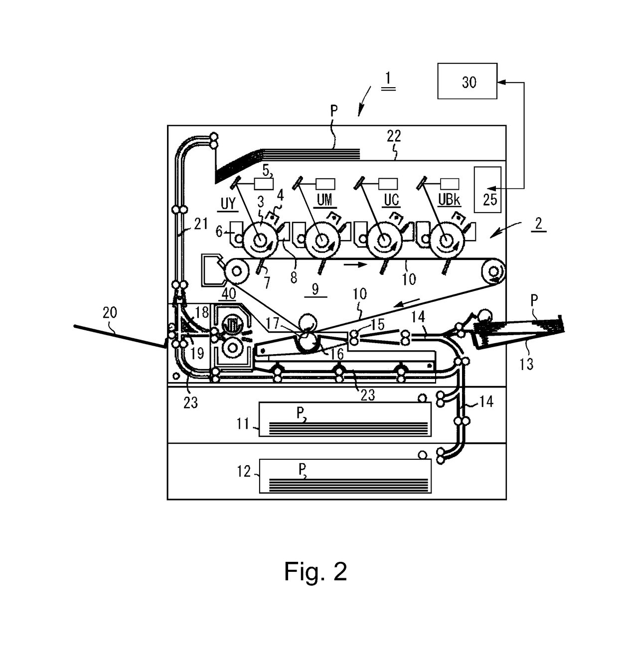
[0027]FIG. 2 is a schematic sectional view of an example of an image forming apparatus 1 in an embodiment. This is image forming apparatus 1 is a four-color-based full-color printer of a tandem type and an intermediary transfer type, using an electrophotographic process. This printer 1 performs an image forming operation on the basis of image information (image signal) inputted from an external terminal 30 such as a personal computer to a controller (main assembly controller, CPU) 25, and is capable of forming a toner image on a recording material (sheet) P and printing out the toner image.

[0028]The recording material P is a sheet-like recording medium capable of permitting formation of the toner image thereon by the printer (image forming apparatus) 1, and as specific example, it is possible to use plain paper having a basis weight of 60-105 g / m2, thick paper having a basis weight of exceeding 106 g / m2, a resin sheet, and the like.

[0029]In the print...


PUM


Abstract

A belt unit includes an endless belt including a metal layer, a heater including a heat generating element, a nip forming member including the heater, a metal stay, a temperature detecting element, a metal leaf spring, an insulating supporting member positioned inside the stay, a cord, and an insulating holder portion including an interposed portion interposed between an exposed portion of the leaf spring and the stay so as to provide insulation therebetween and for holding the supporting member.

Description

FIELD OF THE INVENTION AND RELATED ART[0001]The present invention relates to a belt unit and an image heating apparatus, including the belt unit, suitably used as a fixing device mounted in an image forming apparatus such as a copying machine, a printer, a facsimile machine and a multi-function machine having a plurality of functions of these machines.[0002]Electronic equipment represented by OA (office-automation) equipment such as the copying machine, household electrical appliance equipment, audio equipment or the like includes various electrical component parts.[0003]As a fixing device (image heating apparatus) for use with an image forming apparatus of an electrophotographic type, a fixing device of a film heating type as disclosed in, e.g., Japanese Laid-Open Patent Application (JP-A) 2012-252061 will be described as an example. This fixing device includes a cylindrical fixing film (cylindrical member), a heater (or a halogen lamp) provided inside the fixing film, a pressing p...

Claims


Application Information

Patent Timeline
Patent Type & Authority Applications(United States)
IPC IPC(8): G03G15/20
CPCG03G15/2039G03G15/2053G03G2215/2019G03G15/2042G03G2215/2035
Inventor OKANEMASA, TEMPEI
Owner CANON KK
Why Eureka
Try Eureka