
Cladding for a fuel rod for a light water reactor

a technology for light water reactors and fuel rods, which is applied in the direction of nuclear elements, superimposed coating processes, greenhouse gas reduction, etc., can solve the problems of reducing the aluminum content at the surface of aluminum containing stainless steel coatings, affecting the mechanical and heat treatment conditions, and affecting the performance of the coating. , to achieve the effect of improving the behavior

Inactive Publication Date: 2018-12-20
FRAMATOME ANP
View PDF7 Cites 7 Cited by
  • Summary
  • Abstract
  • Description
  • Claims
  • Application Information

AI Technical Summary

Benefits of technology

The patent aims to improve the behavior of fuel rod cladding tubes in normal and accident conditions. This is achieved by adding a powder mixture containing diffusion elements to enhance corrosion resistance.

Problems solved by technology

Indeed, the mechanical and heat treatment conditions cannot be generally optimized for both the core material and the outer protective material.
Using zirconium-based alloy or of an aluminum containing stainless steel for protecting the molybdenum core against corrosion is further not satisfactory for the following reasons.
Aluminum oxides, which result from the oxidation of the aluminum containing stainless steel coating during the operation of the nuclear reactor, dissolve slowly in water above 300° C. In normal operating conditions, this will lead to a decrease of aluminum content at the surface of the aluminum containing stainless steel coating and therefore to a loss of corrosion protection.
In addition, aluminum oxides swell under irradiation potentially leading to cracks in the protective coating and therefore also to a loss of corrosion protection.

Method used


Image

  • Cladding for a fuel rod for a light water reactor
  • Cladding for a fuel rod for a light water reactor
  • Cladding for a fuel rod for a light water reactor

Examples


Embodiment Construction

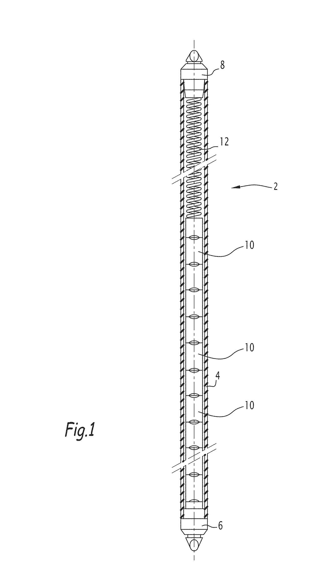
[0051]FIG. 1 illustrates an example of a nuclear fuel rod 2 for a light water reactor. Such a fuel rod is, in particular, intended for a pressurized water reactor (PWR) or for a boiling water reactor (BWR).

[0052]The nuclear fuel rod 2 comprises a cladding 4 in the form of a tube having a circular cross-section closed by a lower plug 6 at its lower end and by an upper plug 8 at its upper end. The nuclear fuel rod 2 contains the nuclear fuel for example in the form of a series of pellets 10 stacked in the cladding 4 and bearing against the lower plug 6. A holding spring 12 is positioned in the upper segment of the cladding 4 in order to bear upon the upper plug 8 and upon the upper pellet 10.

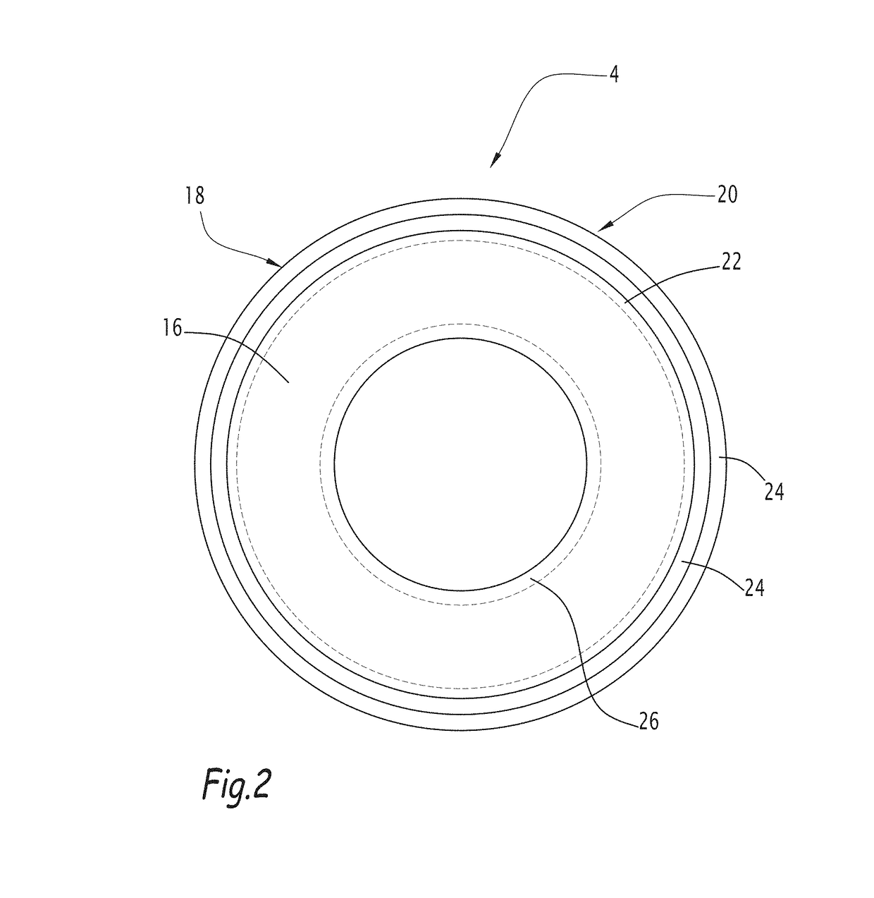
[0053]As shown in FIG. 2, the fuel rod cladding 4 comprises a core 16 and an outer protective layer 18 on the outer side of the core 16.

[0054]The core 16 comprises a matrix consisting of pure molybdenum or of a molybdenum-based alloy.

[0055]In this context, pure molybdenum is to be understood as a ...


PUM

PropertyMeasurementUnit
thicknessaaaaaaaaaa
thicknessaaaaaaaaaa
temperatureaaaaaaaaaa

Abstract

A fuel rod cladding (4) for a light water reactor includes a core (16) including a matrix consisting of pure molybdenum or of a molybdenum-based alloy; and an outer protective layer (18). The outer protective layer (18) is selected among a chromium-based coating (20) deposited on an outer surface of the core (16) that includes at least one chromium-based coating layer (24) consisting of pure chromium or of a chromium-based alloy; a chromium-based diffusion layer (22) obtained by diffusion of chromium into the core (16) from the outer surface of the core (16); or a succession of a chromium-based diffusion layer (22) obtained by diffusion of chromium into the core (16) from the outer surface of the core (16) and a chromium-based coating (20) consisting of chromium or of a chromium-based alloy deposited on the outer surface of said core (16).

Description

[0001]The present invention relates to a cladding tube for a nuclear fuel rod for a light water reactor.BACKGROUND[0002]Cladding tubes for nuclear fuel rods intended for light water reactor (LWR) are usually made of a zirconium-based alloy. Such alloys achieve a highly reliable performance under normal operating conditions of the nuclear reactor. However, they may have a poor behavior under severe accident conditions, particularly in the event of a loss of coolant accident without security injection. Indeed, in high pressure steam conditions, the zirconium alloy cladding will undergo rapid oxidation or corrosion, producing intense heat and hydrogen. At high temperatures, and in particular at temperatures above 800° C., which may occur in accident conditions, the zirconium alloy cladding may further suffer a reduction of its tensile and creep strength, which may result in a deformation or even in a burst of the fuel rods, which can impact reactor core coolability.[0003]Patent applica...

Claims


Application Information

Patent Timeline
Patent Type & Authority Applications(United States)
IPC IPC(8): G21C3/20C23C28/02C23C10/38C23C16/10
CPCG21C3/20C23C28/021C23C28/023C23C10/38C23C16/10G21C3/07C23C10/54Y02E30/30
Inventor HERTZ, DOMINIQUEBISCHOFF, JEREMYGUILLERMIER, PIERRE
Owner FRAMATOME ANP
Features
  • Generate Ideas
  • Intellectual Property
  • Life Sciences
  • Materials
  • Tech Scout
  • Unparalleled Data Quality
  • Higher Quality Content
  • 60% Fewer Hallucinations
Learn More