System and method for supplying lubrication fluid to at least one member of an aircraft propulsion assembly
a technology for aircraft propulsion and lubricating fluid, which is applied in the direction of engines, efficient propulsion technologies, machines/engines, etc., can solve the problems of reducing affecting the performance of the engine, and affecting the operation of the engine, so as to reduce the electronics needed for controlling and avoid drawbacks
- Summary
- Abstract
- Description
- Claims
- Application Information
AI Technical Summary
Benefits of technology
Problems solved by technology
Method used
Image
Examples
first embodiment
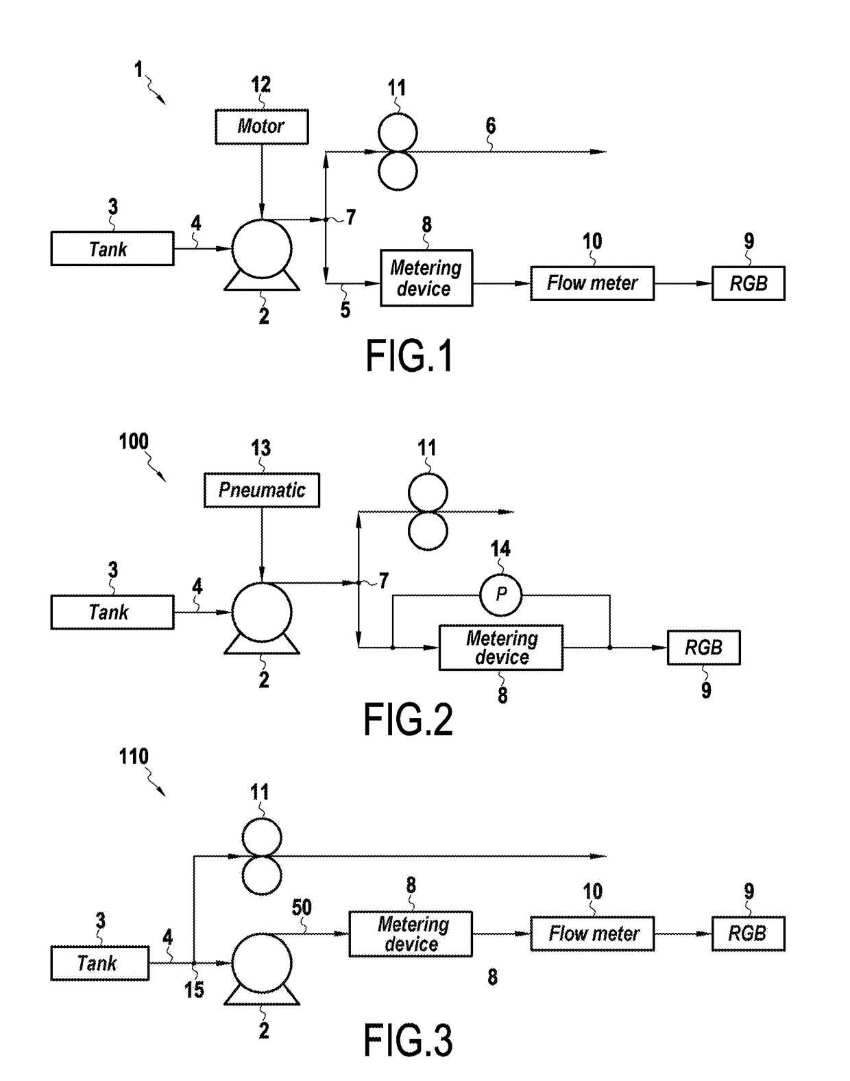
[0065]FIG. 1 is a diagram of an oil feed system 1 for a reduction gearbox (RGB) of an aeroengine that comprises a turbine engine.
[0066]In the embodiment shown in FIG. 1, the feed system 1 comprises a centrifugal pump 2 having its inlet connected to a fuel tank 3 via a feed branch 4 of the centrifugal pump 2, and two delivery branches 5 and 6 connected to the outlet of the centrifugal pump 2 via a separator node 7.
[0067]The first delivery branch 5 includes fluid metering device 8 with a metering slot connected to an RGB 9 via a flow meter 10.
[0068]The oil metering device 8 with a metering slot is itself known. By way of example, it may be in the form of a slide and a sheath typically used for metering fuel, as mentioned in Document FR 2 950 864. The controlled movement of the slide in the sheath or bushing masks the slot to a greater or lesser extent. The uncovered section of the slot through which the fluid passes is thus controlled depending on the desired flow rate. Movement of th...
second embodiment
[0082]FIG. 2 is a diagram of an oil feed system 100 for an RGB of an aeroengine comprising a turbine engine.
[0083]Elements that are identical to the feed system 1 of FIG. 1 are given the same numerical references.
[0084]The feed system 100 of the second embodiment differs from the first embodiment in that the centrifugal pump 2 is driven at a variable speed by a pneumatic drive 13 operating on air taken from a compressor of the engine.
[0085]The pneumatic drive 13 is configured so that the drive speed range of the centrifugal pump 2 lies within a range defined relative to a minimum speed. The operating range is defined so that the operating speed lies in the range 1.2 times the minimum speed and twice the minimum speed.
[0086]The feed system 100 of the second embodiment also differs from the first embodiment in that the flow meter is replaced by a pressure sensor 14 connected between the inlet and the outlet of the oil metering device 8. Such a configuration is independent of the type ...
third embodiment
[0087]FIG. 3 is a diagram showing a system 110 for feeding oil to an RGB of an aeroengine comprising a turbine engine.
[0088]Elements that are identical with the feed system 1 of FIG. 1 are given the same numerical references.
[0089]This third embodiment differs from the first embodiment in that it does not have a separator node at the outlet from the centrifugal pump 2 since there is only the first branch 5 connected to the outlet of the centrifugal pump 2, with the second branch 6 having the positive-displacement pump 11 being connected directly to the tank via a separator node 15 provided in the feed branch 4. The oil tank 3 generally needs to be pressurized so as to ensure there is sufficient oil pressure at the inlet to the positive-displacement pump 11, in particular in order to avoid any risk of cavitation in the pump 11.
[0090]In a utilization of an oil feed system of the invention, that can be applied to any embodiment of the feed system, provision may be made in the event of ...
PUM
 Abstract
Description
Claims
Application Information
 - R&D
- Intellectual Property
- Life Sciences
- Materials
- Tech Scout
- Unparalleled Data Quality
- Higher Quality Content
- 60% Fewer Hallucinations
Browse by: Latest US Patents, China's latest patents, Technical Efficacy Thesaurus, Application Domain, Technology Topic, Popular Technical Reports.
© 2025 PatSnap. All rights reserved.Legal|Privacy policy|Modern Slavery Act Transparency Statement|Sitemap|About US| Contact US: help@patsnap.com

