X-Ray Tube Casing

a technology for x-ray tubes and casings, applied in the field of x-ray tubes, can solve the problems of increasing the cost of the system, increasing material and manufacturing costs, and particularly challenging, and achieve the effects of reducing the weight and size of the casing, improving the cooling capacity and x-ray shielding capabilities of the casing

Active Publication Date: 2018-12-27
GENERAL ELECTRIC CO
View PDF5 Cites 9 Cited by
  • Summary
  • Abstract
  • Description
  • Claims
  • Application Information

AI Technical Summary

Benefits of technology

[0018]As a result, it is desirable to develop a structure, method of manufacture and method for use of an improved x-ray tube casing that is designed to reduce the weight and size of the casing while improving the cooling capacity and x-ray shielding capabilities of the casing when in use.

Problems solved by technology

This is particularly challenging at joint transitions between parts of the housing 12′.
This is negative for a number of reasons:increased material and manufacturing costs for the assembly of the casing 10′ using the excess lead sheet 14′;the handling and installation of the x-ray tube casing 10′ is difficult due to the increased weight of the casing 10′, normally requiring more than one person or mechanical assists; andthe structure of the gantry or positioner of the medical imaging system must be more substantial to handle the increased weight of the casing 10′ which increases the cost of the system.
Further, the size of the tube casing 10′, including the heat exchanger 24′ / cooling circuit 25′ mounted to the exterior of the casing 10′, limits the degree of oblique imaging angles around the patient and can compromise the quality of exam performed.

Method used


Image

  • X-Ray Tube Casing
  • X-Ray Tube Casing
  • X-Ray Tube Casing

Examples


Embodiment Construction

[0040]In the following detailed description, reference is made to the accompanying drawings that form a part hereof, and in which is shown by way of illustration specific embodiments, which may be practiced. These embodiments are described in sufficient detail to enable those skilled in the art to practice the embodiments, and it is to be understood that other embodiments may be utilized and that logical, mechanical, electrical and other changes may be made without departing from the scope of the embodiments. The following detailed description is, therefore, not to be taken in a limiting sense.

[0041]Exemplary embodiments of the invention relate to an X-ray tube system including an increased emitter area to accommodate larger emission currents in conjunction with microsecond X-ray intensity switching in the X-ray tube. An exemplary X-ray tube and a computed tomography system employing the exemplary X-ray tube are presented.

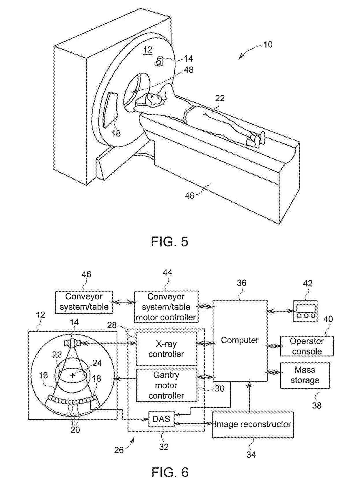
[0042]Referring now to FIGS. 5 and 6, a computed tomography (...


PUM


Abstract

An x-ray tube casing is provided which includes a central frame having internal passages to supply a cooling fluid directly to the casing without the need for an external dedicated heat exchanger. The cooling fluid flowing through the passages in the easing can thermally contact the dielectric coolant within the casing to cool the tube coolant during operation of the x-ray tube. The casing is formed in an additive manufacturing process to allow for tight tolerances with regard to the structure for the casing and the internal passages to reduce the size and weight of the casing. The casing can additionally be formed from a metal matrix including a metal with high x-ray attenuation and a filler metal. The metal matrix eliminates the need for a separate x-ray attenuation layer within the casing, further reducing the size, number of parts and assembly complexity of the casing.

Description

BACKGROUND OF THE INVENTION[0001]The invention relates generally to x-ray tubes, and more particularly to a casing for enclosing the various components of the x-ray tube insert.[0002]X-ray systems may include an x-ray tube, a detector, and a support structure for the x-ray tube and the detector. In operation, an imaging table, on which an object is positioned, may be located between the x-ray tube and the detector. The x-ray tube typically emits radiation, such as x-rays, toward the object. The radiation passes through the object on the imaging table and impinges on the detector. As radiation passes through the object, internal structures of the object cause spatial variances in the radiation received at the detector. The detector then sends data received, and the system translates the radiation variances into an image, which may be used to evaluate the internal structure of the object. The object may include, but is not limited to, a patient in a medical imaging procedure and an in...

Claims


Application Information

Patent Timeline
Patent Type & Authority Applications(United States)
IPC IPC(8): H05G1/04H01J35/16H05G1/02H01J35/06H01J35/24
CPCB33Y80/00H05G1/025H05G1/04H01J5/02H01J35/065H01J35/16H01J35/24H05G1/02
Inventor ROGERS, CAREY SHAWNDESROSIERS, ANDREW J.KARESH, MATTHEW
Owner GENERAL ELECTRIC CO
Why Eureka
Try Eureka