

Floor panel having drainage protrusions
a technology of floor panels and protrusions, applied in the field of floor panels, can solve the problems of affecting the appearance of décor, affecting the appearance of the room, and not being suitable for outdoor use or wet areas,
- Summary
- Abstract
- Description
- Claims
- Application Information
AI Technical Summary
Benefits of technology
Problems solved by technology
Method used
Image

Examples
Embodiment Construction
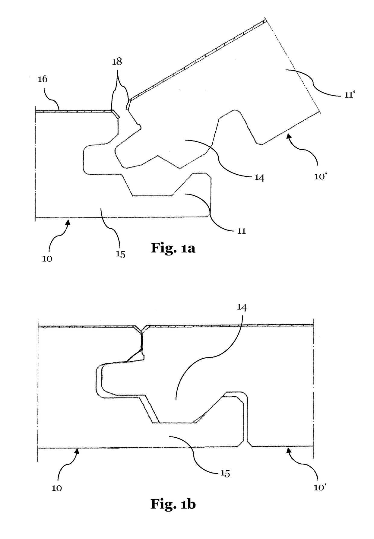
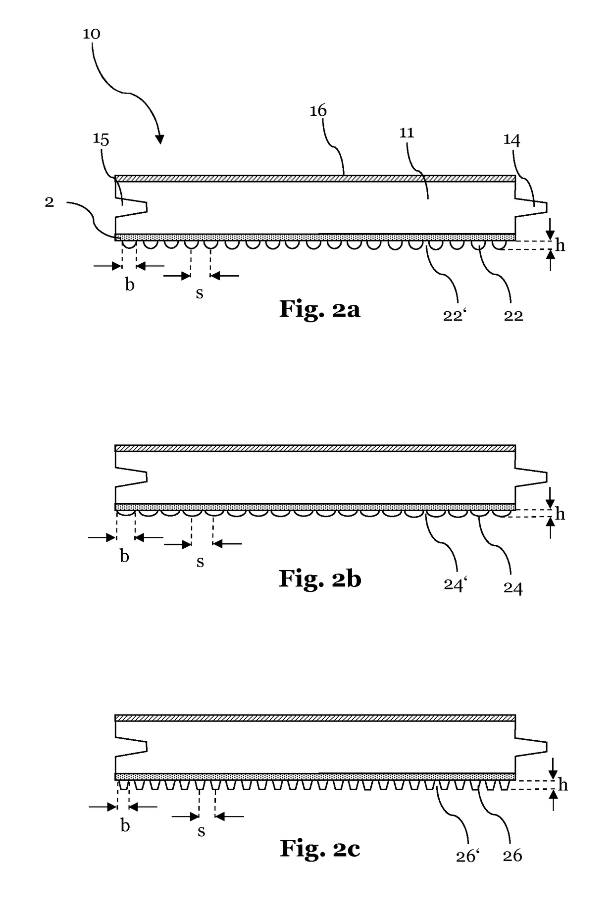
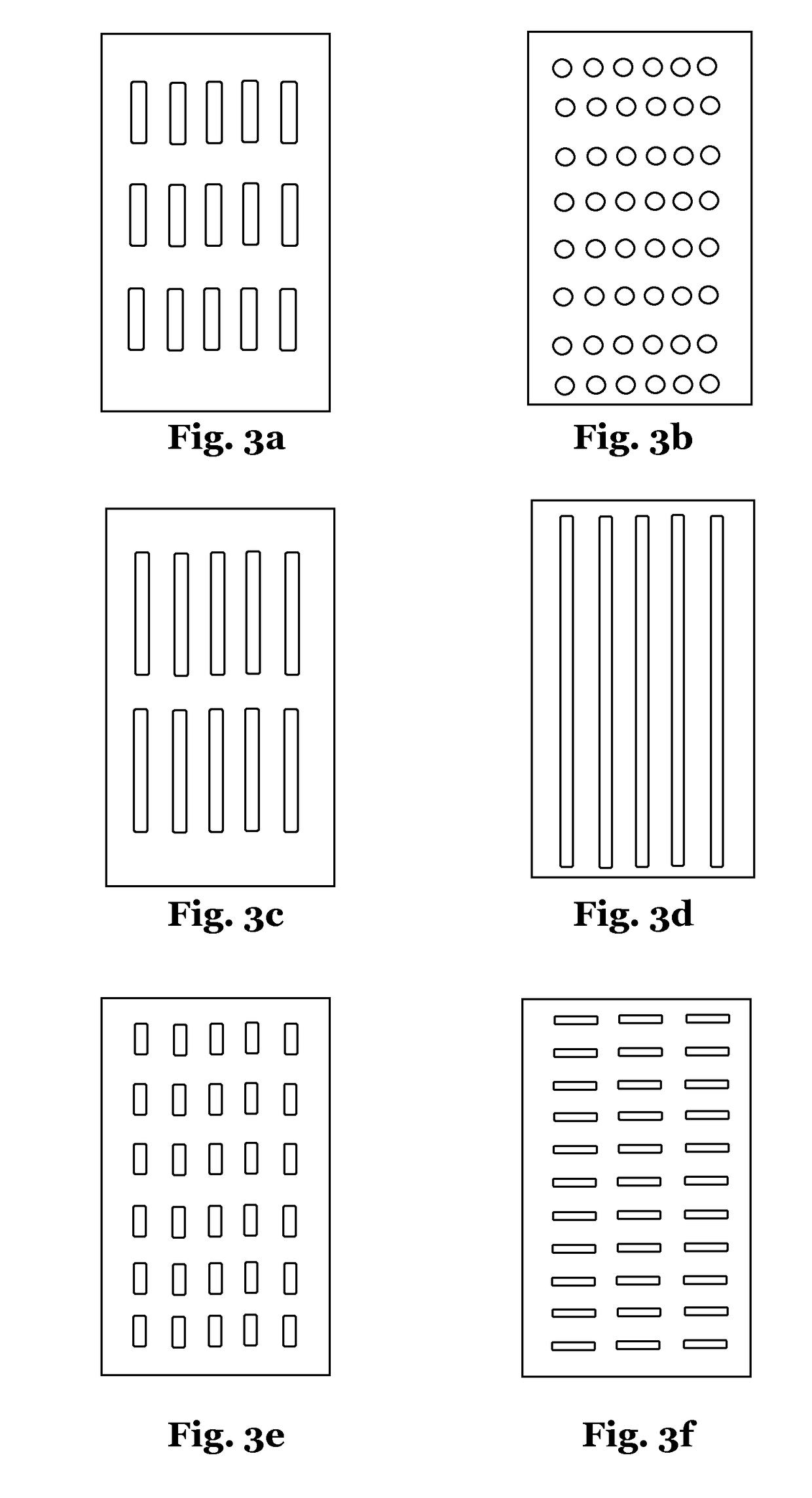
[0007]The floor panels of the present invention include a carrier plate having a front face and rear face, wherein the carrier plates are provided with a décor and / or protective layer on their front face. On the sides, the carrier plate comprises preferably coupling means in the form of tongue and groove elements, which allow a connection of multiple similar panels in directions parallel to the front face as well as perpendicular to the front face by means of form fit. The coupling means are preferably provided on all sides respectively edges of the floor panels. On the rear face of the carrier plate, drainage protrusions are provided. The drainage protrusions are therefore fixedly connected with the carrier plate or integrally formed with the carrier plate, such that during installation of such floor panels no separate surface drainages in form of e.g. meshes are necessary (although, these can be used additionally, if it should be desired or necessary). Since the drainage protrusio...
PUM
| Property | Measurement | Unit |
|---|---|---|
| heat resistance | aaaaa | aaaaa |
| width | aaaaa | aaaaa |
| width | aaaaa | aaaaa |
Abstract
Description
Claims
Application Information