Centering a Line in a Rotating Shaft

a technology of rotating shaft and centering tube, which is applied in the direction of electric cable installation, wind motor, and cable arrangement between relatively moving parts, can solve the problems of preventing reliable connection of lines and cable fractures, and achieves convenient introduction of devices into hollow shafts, ensuring the centering of tubes, and adequate rigidity.

Inactive Publication Date: 2019-01-03
SENVION GMBH
View PDF5 Cites 0 Cited by
  • Summary
  • Abstract
  • Description
  • Claims
  • Application Information

AI Technical Summary

Benefits of technology

The invention describes a device that allows for centering lines in a rotating shaft, reducing flexing movement and associated disadvantages. The lines are placed in a tube, which is then inserted into the rotating shaft. The tube has slotted walls that can be widened to allow for easy line introduction and removal. The ends of bristle tufts on the tube outer side rest on the inner wall of the shaft, allowing the tube to be keep centrally in the shaft. The device can be connected to other devices to form a composite. The technical effect is to improve the stability and reliability of the device for high-speed rotation.

Problems solved by technology

In addition, the continuous movement in the case of electric lines can lead to cable fractures, which likewise regularly require a stoppage of the system and a line replacement.
Not least, the movements can be propagated into axial movements at the line ends, which can impede a reliable connection of the lines.

Method used


Image

  • Centering a Line in a Rotating Shaft
  • Centering a Line in a Rotating Shaft
  • Centering a Line in a Rotating Shaft

Examples


Embodiment Construction

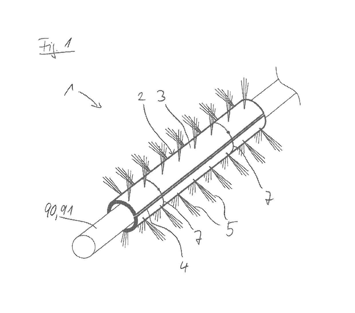
[0037]A first exemplary embodiment of a device 1 according to the invention is illustrated in FIG. 1.

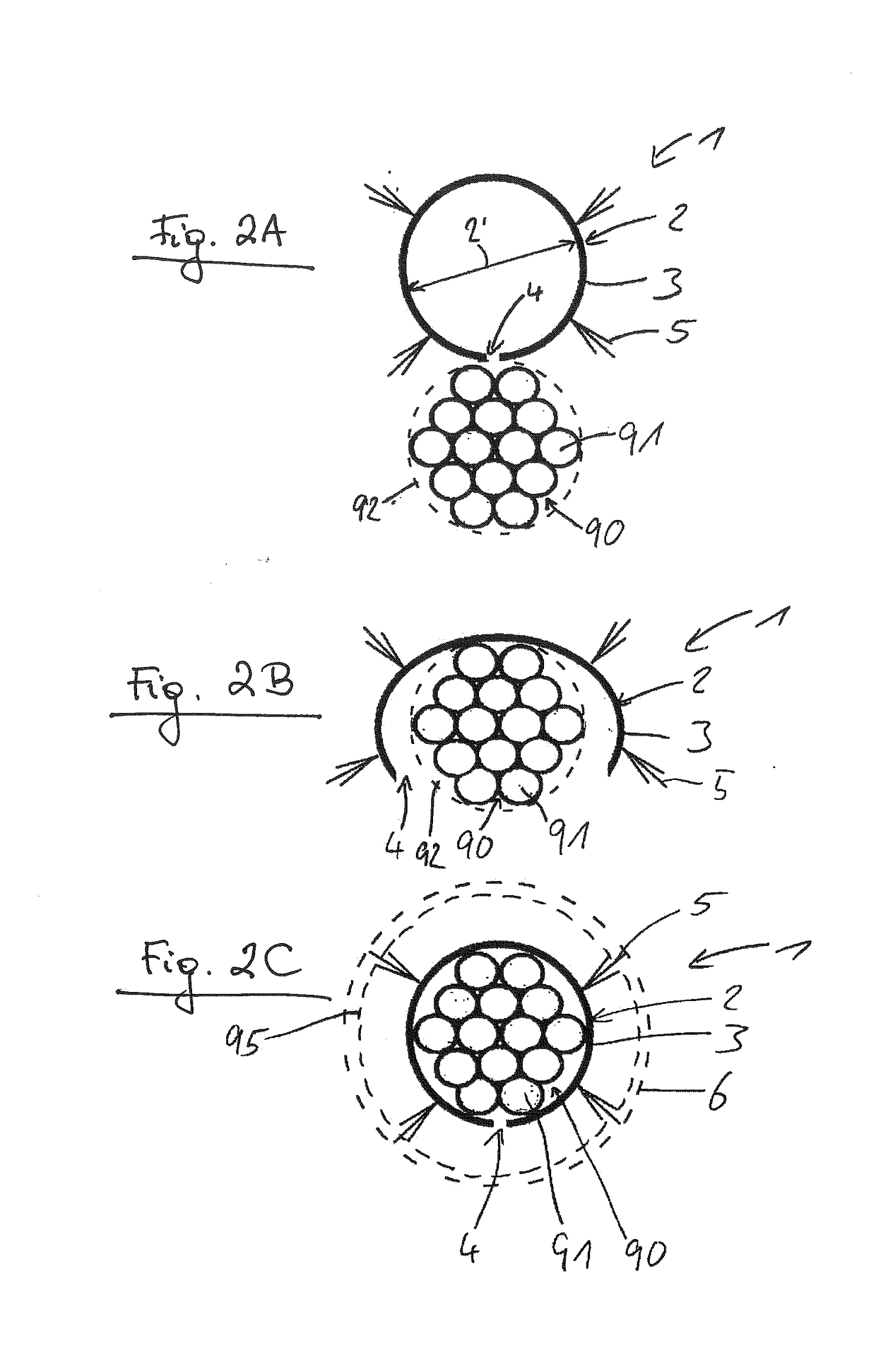
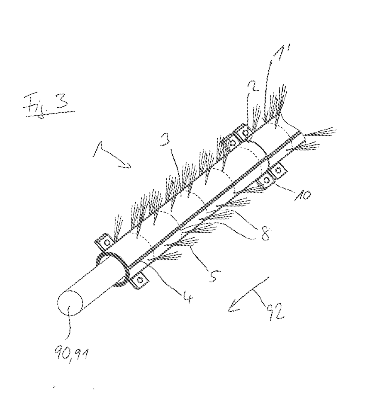
[0038]The device 1 comprises a tube 2 of plastic, the wall 3 of which is provided over the entire tube length with a slot 4 parallel to the tube axis. The plastic is chosen to be elastic, such that the slot 4 can be deformed for the radial introduction of a line bundle 90 or an individual line 91 into the tube 2.

[0039]Arranged on the outer side of the tube 2, distributed in a regular grid in the longitudinal and circumferential direction are bristle tufts 5, which project at right angles to the outer side of the tube 2.

[0040]The longest bristles of the bristle tufts 5 define the external diameter of the device 1. This external diameter is chosen such that it is larger by 5% than the internal diameter of that hollow shaft into which the device 1 is to be inserted. Following the insertion into just this hollow shaft, the line bundle 90 is held centered by the bristle tufts 5, which res...


PUM


Abstract

The device for centering a line in a rotating hollow shaft comprises a tube, the wall of which is slotted over the entire tube length, substantially parallel to the tube axis, and which can be deformed for the temporary widening of the slot for the radial introduction of a line into the tube. Bristle tufts distributed in the longitudinal and circumferential direction are arranged on the outer side of the tube for support on the inner wall of the rotating hollow shaft. In the wind turbine having a rotor rotatably supported on a gondola around a rotor shaft formed as a hollow shaft, wherein at least one line is led from the rotor through the rotor shaft to the gondola, the line guidance in the rotor shaft is implemented as an arrangement according to the invention.

Description

BACKGROUND[0001]The invention relates to a device for centering a line in a rotating shaft, an arrangement of a line in a rotating shaft comprising such a device, and a wind turbine with corresponding arrangement.[0002]In systems having two parts rotating relative to each other, it is regularly necessary to produce line connections between the two parts in order, for example, to permit electric power or signal transmission. The corresponding lines are regularly lead through the shafts provided for the rotation to a slip ring arrangement, where, via an arrangement of one slip ring assigned to one part of the system and a receiver (for example a carbon brush) resting on the slip ring and assigned to the other part of the system, an electrical connection is produced between the two parts of the plant. For hydraulic lines, recourse is often had to a cascade of rotary couplings arranged congruently with the shaft axis.[0003]One example of systems having two parts rotating relative to eac...

Claims


Application Information

Patent Timeline
IPC IPC(8): F03D80/80
CPCF03D80/85F05B2240/61F05B2240/21F03D80/00H02G1/08H02G3/04H02G3/0481H02G11/00Y02E10/72
Inventor KA NER, MIRKO
Owner SENVION GMBH
Why Eureka
Try Eureka