Displacement detecting device

a technology of displacement detection and detecting device, which is applied in the direction of measurement device, optics, instruments, etc., can solve the problems of limited mechanical response frequency of upward/downward movement of the objective lens, decrease in the resolution of measurement during expansion of the measurement range, and low sensitivity, so as to achieve the effect of widening the use condition and controlling the heat generated in us

Active Publication Date: 2019-01-10
DMG MORI SEIKI CO LTD
View PDF0 Cites 2 Cited by
  • Summary
  • Abstract
  • Description
  • Claims
  • Application Information

AI Technical Summary

Benefits of technology

[0018]According to a displacement detecting device of the present invention, a driving mechanism in a related art is not necessary. Thus, heat generated in use can b...

Problems solved by technology

However, in this method, there is a problem of being easily influenced by an inclination of a measured surface, of low sensitivity, and of a decrease in resolution of measurement during expansion of a measurement range.
Thus, a mechanical response frequency of the upward/downward movement of the objective lens is limited by a structure or weight of the actuator.
As a result, in the displacement detecting...

Method used


Image

  • Displacement detecting device
  • Displacement detecting device
  • Displacement detecting device

Examples


first embodiment

1. First Embodiment of Displacement Detecting Device

[0052]First, the first embodiment (hereinafter, referred to as “present embodiment”) of the displacement detecting device of the present invention will be described with reference to FIG. 1 to FIG. 3.

[0053]1-1. Configuration Example of Displacement Detecting Device

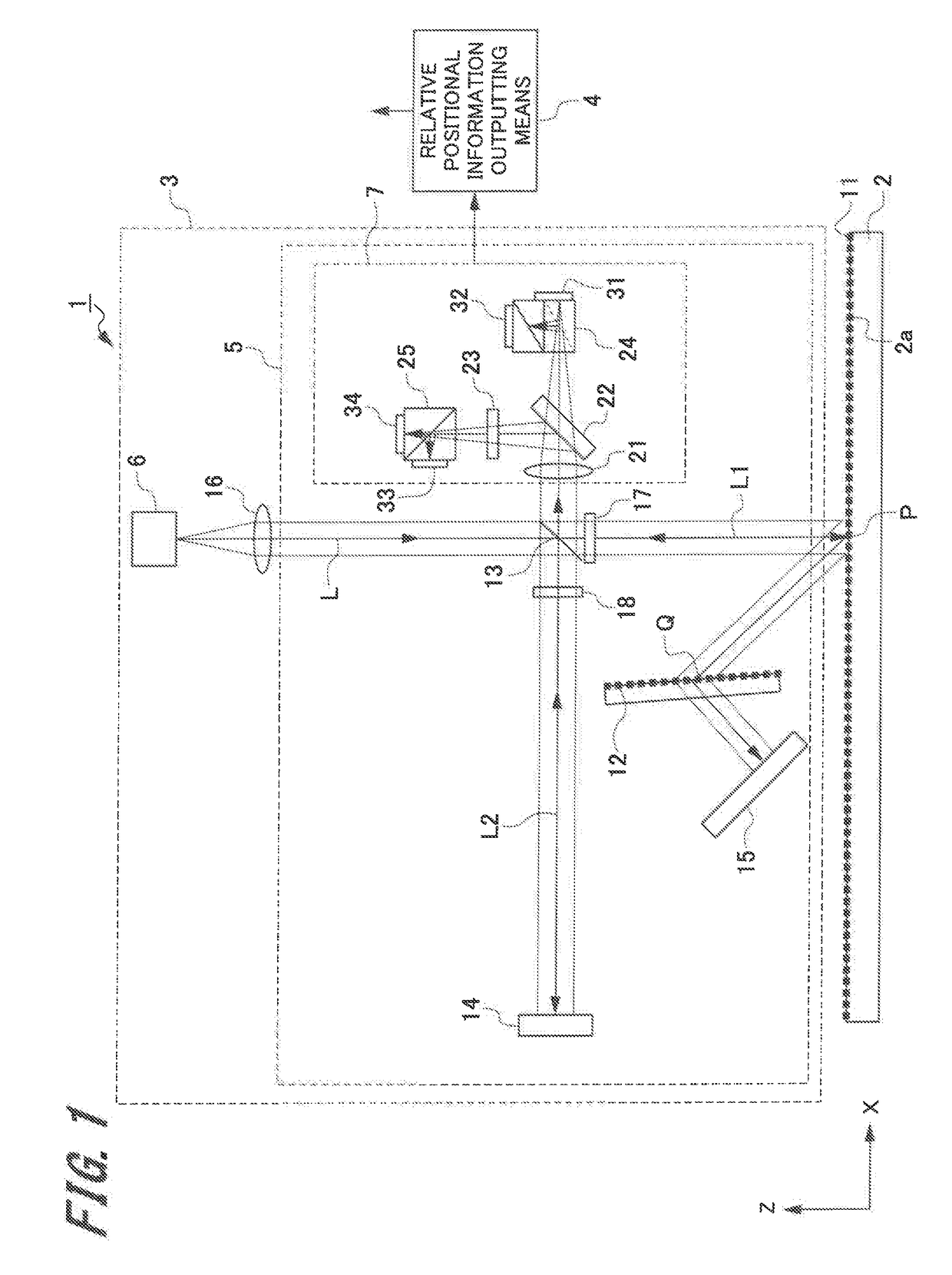
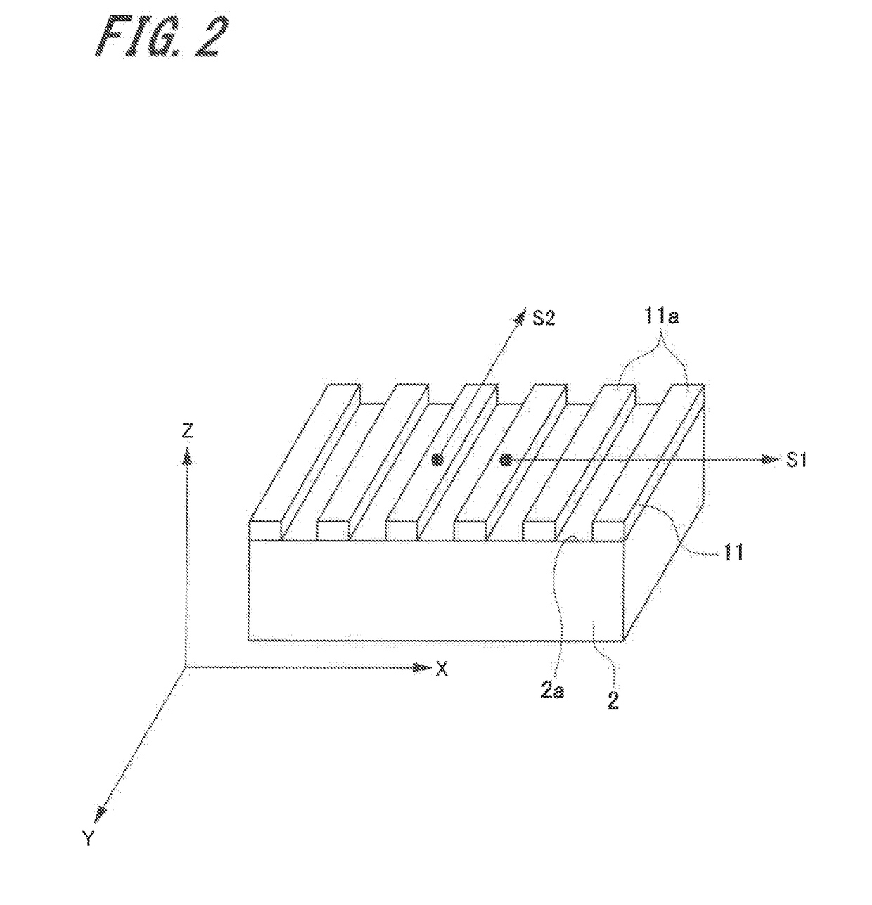
[0054]FIG. 1 is a schematic configuration view illustrating a configuration of the displacement detecting device. FIG. 2 is a perspective view illustrating a measured member in which a first diffraction grating is provided in the displacement detecting device.

[0055]A displacement detecting device 1 of the present embodiment is a displacement detecting device that detects displacement (movement amount) of when at least one of a head and a measured member is moved.

[0056]As illustrated in FIG. 1, the displacement detecting device 1 includes a first diffraction grating 11 provided on a measured surface 2a of a measured member 2, a head 3, and a relative positional information...

second embodiment

2. Second Embodiment

[0156]Next, a displacement detecting device according to the second embodiment will be described with reference to FIG. 6 and FIG. 7.

[0157]FIG. 6 is a schematic configuration view illustrating a configuration of the displacement detecting device according to the second embodiment, and FIG. 7 is a block diagram illustrating a relative positional information outputting means in the displacement detecting device according to the second embodiment.

[0158]A displacement detecting device 101 according to the second embodiment is a displacement detecting device that can output two-dimensional displacement information in a first direction X and a third direction Z. Thus, here, the same sign is assigned to a common part with the displacement detecting device 1 according to the first embodiment, and an overlapped description is omitted.

[0159]As illustrated in FIG. 6, a displacement detecting device 101 includes a measured member 2 in which a first diffraction grating 111 is...

third embodiment

3. Third Embodiment

[0177]Next, a displacement detecting device according to the third embodiment will be described with reference to FIG. 8 to FIG. 12B.

[0178]FIG. 8 is a schematic configuration view illustrating a configuration of the displacement detecting device according to the third embodiment. FIG. 9 is a schematic configuration view illustrating a configuration of a first displacement detecting unit and a second displacement detecting unit in the displacement detecting device according to the third embodiment. FIG. 10 is a schematic view illustrating a configuration of a third displacement detecting unit and a fourth displacement detecting unit in the displacement detecting device according to the third embodiment. FIG. 11 is a block diagram illustrating a relative positional information outputting means in the displacement detecting device according to the third embodiment. FIG. 12A and FIG. 12B are views illustrating a first diffraction grating in the displacement detecting ...


PUM


Abstract

A displacement detecting device includes a first diffraction grating, a light source, a displacement detecting unit, and a light receiving unit. The displacement detecting unit includes a light flux dividing unit, a second diffraction grating, and a reference reflecting member. An incident angle of a first light flux to the first diffraction grating, a diffraction angle of the first diffraction grating, an incident angle of the first light flux to the second diffraction grating, and a diffraction angle of the second diffraction grating are angles at which a displacement amount in an optical path length of the first light flux from the light flux dividing unit to the first diffraction grating and a displacement amount in an optical path length of the first light flux from the first diffraction grating to the second diffraction grating become equal in a case where a measured member is displaced in a direction orthogonal to a measured surface.

Description

BACKGROUNDTechnical Field[0001]The present invention relates to a displacement detecting device to detect displacement of a measured surface by a non-contact sensor using light emitted from a light source, and specifically relates to a technology of detecting displacement in a vertical direction of a measured surface.Related Art[0002]In related arts, a displacement detecting device using light is widely used as a device of measuring displacement or a shape of a measured surface in a non-contact manner. As a representative example, there is a method of emitting a laser beam to a measured surface and detecting a change in a position of reflection light by a PSD. However, in this method, there is a problem of being easily influenced by an inclination of a measured surface, of low sensitivity, and of a decrease in resolution of measurement during expansion of a measurement range.[0003]On the other hand, there is a method of using a Michelson interferometer with a measured surface as a m...

Claims


Application Information

Patent Timeline
IPC IPC(8): G01B9/02G02B27/42G02B27/28G02B27/14
CPCG01B9/02041G02B27/4233G01B9/02011G02B27/283G02B27/14G02B27/4277G01B9/02019G01B9/02027G01B9/021G01B9/02018G01B2290/70G01B2290/20
Inventor TAMIYA, HIDEAKINODA, KAZUKI
Owner DMG MORI SEIKI CO LTD
Why Eureka
Try Eureka