
Method, transmission unit, system and computer program for wireless communication between a camera and at least one remote flash device

a technology of remote lighting and transmission unit, applied in the field of communication, can solve the problems of difficult or even impossible to satisfy all requirements for complete operability, remote lighting device not providing any information back, and inconvenient arrangement of flashes, etc., to achieve compatibility between devices, simplify the process, and avoid over-complicated signaling

Active Publication Date: 2019-01-10
PROFOTO
View PDF0 Cites 1 Cited by
  • Summary
  • Abstract
  • Description
  • Claims
  • Application Information

AI Technical Summary

Benefits of technology

The present invention allows for better communication between camera equipment and external flash devices, even if they are not from the same brand. This is achieved by standardizing the signaling between the camera and the remote flash devices, and by attaching the intermediate radio transmission unit to the hot shoe connector of the camera. The invention also allows for flexibility in adapting the operational properties of the intermediate radio transmission unit to the camera and allows new producers of communication devices to enter the market and compete with established producers. Overall, the invention makes it easier for photographers to use various flash devices with different brands and models.

Problems solved by technology

Historically, flashes were produced by means of rather inconvenient arrangements, such as single-use flashbulbs and flammable powders.
Since standardization available in the field is allowing for deviations with respect to certain more advanced functions, both mechanically and electronically, it is in practice hard or even impossible to satisfy all requirements if complete operability is requested.
However, according to this control system, the remote lighting devices are not providing any information back to the flash lighting device in the hot shoe connector of the camera body.
Using camera and flash or similar lighting systems presently available on the market means that the choice of camera in practice limits the choice of flash device or related lighting device, or alternatively, in the sense that a flash or lighting device limits the choice of camera.
For an amateur photographer who is in possession of a flash device, which cannot be used any longer together with certain camera equipment because of the above mentioned limitation, this may be greatly discouraging.
For a professional photographer, or a commercial studio environment collaborating with many different photographers with varying preferences in their choice of camera equipment, this may be a severe limitation.
To overcome the limitation, professional studios are typically obliged to be equipped with numerous brands of flash devices, so as to accommodate the needs of any professional photographer, and as a consequence the costs to the studio are substantially increased.
Another problem when using flash or similar lighting systems presently available on the market is that is can in some situations be hard to determine if TTL-mode or manual mode should be used.
One mode is not always better than the other.
However, having to modify the lighting devices to be used to various camera bodies is highly undesired.
In addition to that, there is no way of overcoming the limitation that use of numerous lighting devices together with one camera is impossible, unless all lighting devices are produced by the same vendor and thus are recommended and fully compatible with the camera equipment in use.
When consideration is made to a standard type of studio environment, lighting devices of different types and brands are often hinged near the ceiling of the studio and therefore in practice impossible to adjust or substitute components on, only to be usable together with various cameras.
However, despite this incentive, and despite prior attempts to overcome problems relating to the limited choice of equipment due to lacking interoperability, there is presently no solution available.
No such flash devices have yet been developed.

Method used


Image

  • Method, transmission unit, system and computer program for wireless communication between a camera and at least one remote flash device
  • Method, transmission unit, system and computer program for wireless communication between a camera and at least one remote flash device
  • Method, transmission unit, system and computer program for wireless communication between a camera and at least one remote flash device

Examples


Embodiment Construction

[0028]Throughout this document, the term flash refers either to the flash of light itself or to the electronic flash unit discharging the light.

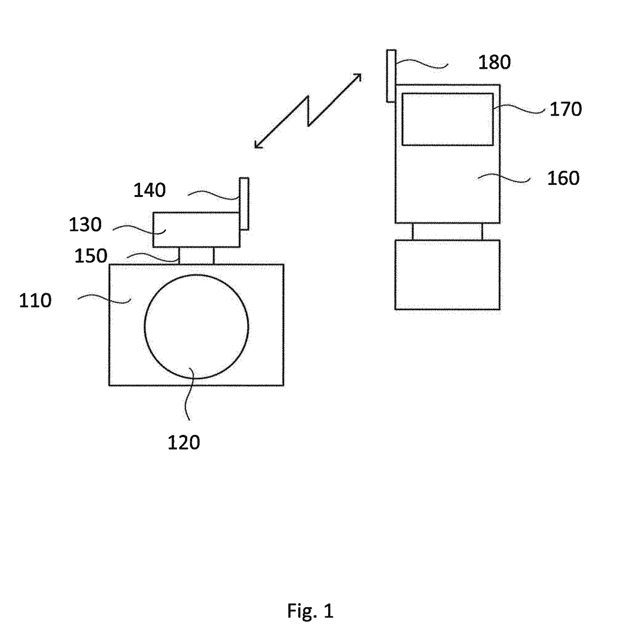
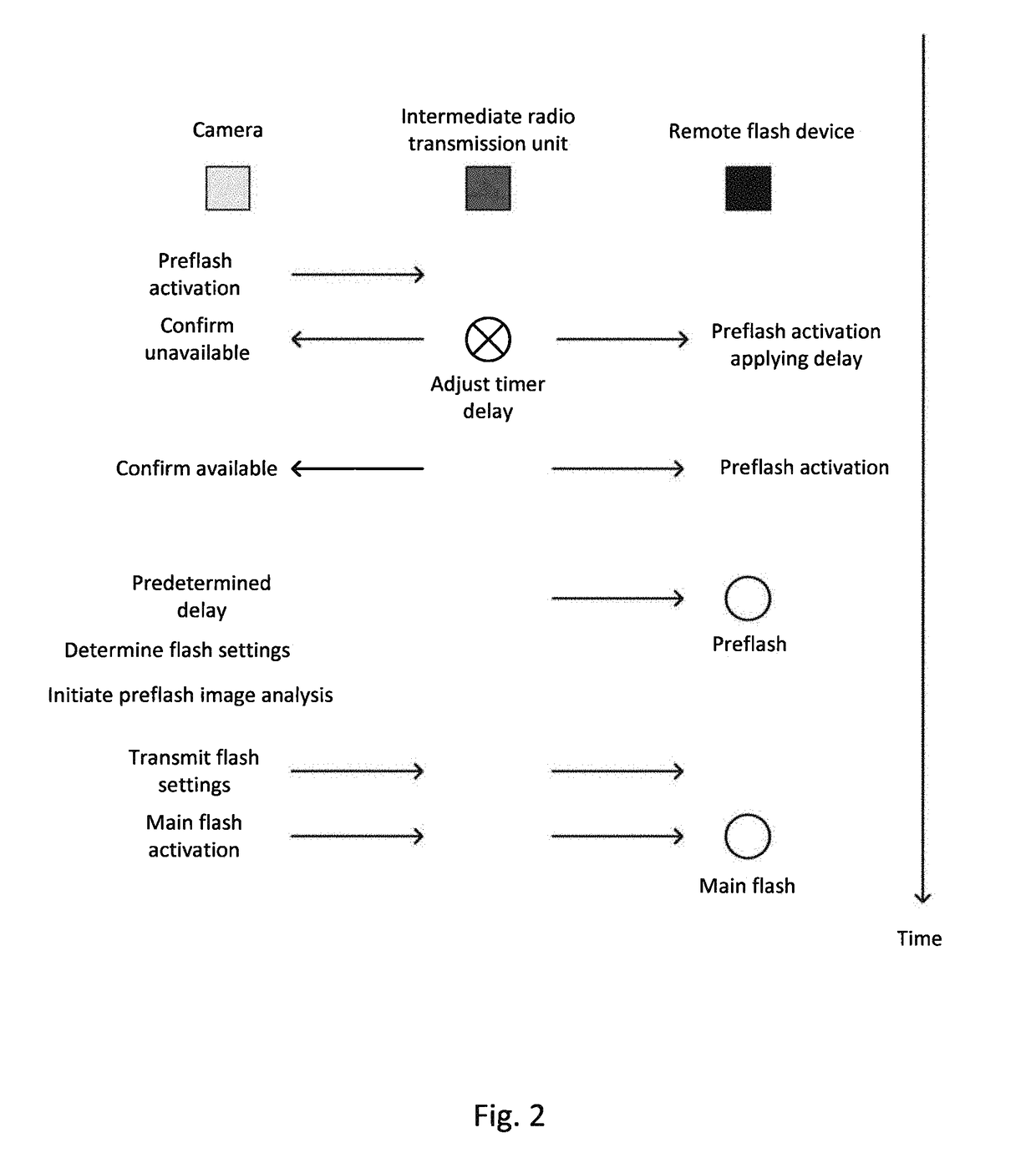
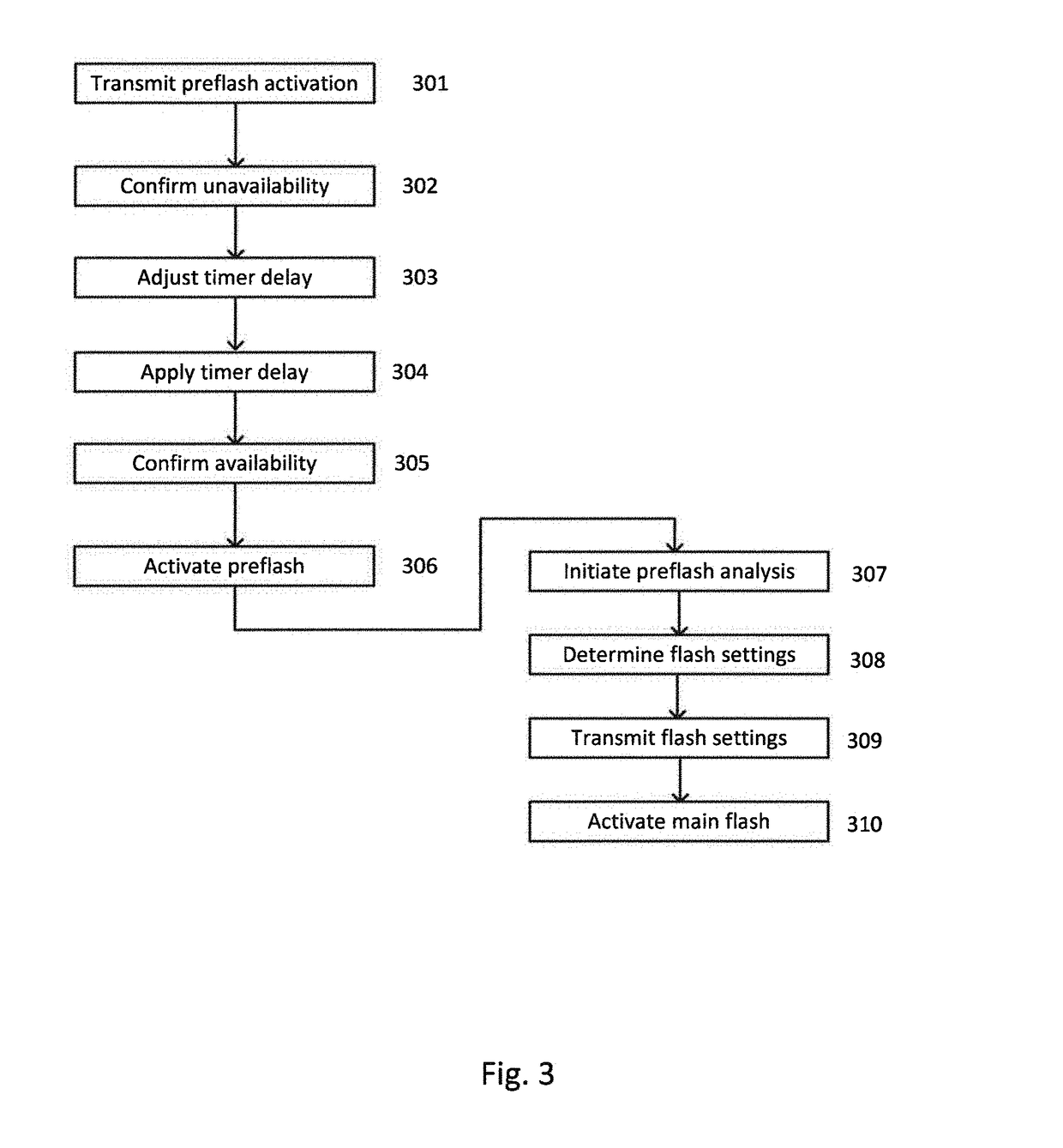
[0029]Through-the-lens (TTL) flash photographic control originally appeared in about 1980 in analogue form and has later been transformed into digital TTL, which is even more accurate also allows for more advanced functionality. The main features of digital TTL are that prior to the actual exposure and the firing of the main flash, one or more small flashes called preflashes are emitted. The light returning through the lens is measured and this value is used to calculate the amount of light necessary for the actual exposure. Multiple preflashes can be used to improve the flash output. Canon refers to this technique as “E-TTL” and has recently improved the system with a new generation “E-TTL II”. The first form of digital TTL by Nikon, called “D-TTL”, was originally introduced, and since then, the superior “i-TTL” system has been promoted. Fr...


PUM


Abstract

The present invention generally relates to the field of communication between electronic devices used for photography. In particular, the invention relates to a method, transmission unit, system and computer program for wireless communication between a camera and at least one remote flash device, such as photoflash units and related equipment. More in particular, the invention provides a way of controlling a plurality of flash devices from an intermediate radio transmission unit mountable on the camera, and utilized a delay a sequence flash control sequence so as to synchronize the function of the camera and the remote flash devices during image acquisition. Further the invention provides a way of controlling in the photoflash units settings for the main flash, wherein the setting are the last settings determined by the camera when the intermediate radio transmission unit was in a TTL-mode.

Description

TECHNICAL FIELD[0001]The present invention generally relates to the field of communication between electronic devices used for photography. In particular, the invention relates to a method, transmission unit, system and computer program for wireless communication between a camera and at least one remote flash device, such as photoflash units and related equipment.BACKGROUND ART[0002]Photoflash units, also called flash devices, flash lighting devices etc, of various kinds are commonly used in photography for producing a flash of artificial light to help illuminate a scene, a scene which would otherwise be perceived as underexposed, i.e. too dark, to the viewer of a captured picture of the scene. Other uses of flashes are capturing quickly moving objects or changing the quality of light. Most current flash lighting devices are electronic and have been developed through xenon-based flash devices to state of the art light emitting diode (LED) flash devices. Historically, flashes were pr...

Claims


Application Information

Patent Timeline
Patent Type & Authority Applications(United States)
IPC IPC(8): H04N5/235H04N5/067G03B15/05H04M1/725G03B15/03H04M1/72412
CPCH04N5/2354H04N5/2351H04N5/067H04M1/7253G03B2215/0557G03B2206/00G03B15/05H04M1/72412H04N23/74H04N23/71
Inventor FALK, ANTON
Owner PROFOTO
Learn More