
Installation for charging electric cars

a technology for charging electric cars and electric cars, applied in electrochemical generators, battery/fuel cell control arrangements, transportation and packaging, etc., can solve the problems of generating a considerable amount of waste heat, low loss, and short charging time, and achieve the effect of reducing the space requiremen

Active Publication Date: 2019-01-17
DR ING H C F PORSCHE AG
View PDF0 Cites 4 Cited by
  • Summary
  • Abstract
  • Description
  • Claims
  • Application Information

AI Technical Summary

Benefits of technology

The invention is a solution for cooling components in a small space, which makes it easier to arrange different equipment variants and reduces installation costs. The invention allows for highly scalable power and flexible positioning on-site. It also has low-noise and slim charging outputs, which makes it user-friendly. Additionally, the invention has scalable cooling power and requires less space than conventional solutions.

Problems solved by technology

Since the direct-current connections of the charging column are connected directly to corresponding connections of the traction battery, high charging currents can be transmitted with a low level of loss, this allowing short charging times but also generating a considerable amount of waste heat.

Method used


Image

  • Installation for charging electric cars
  • Installation for charging electric cars
  • Installation for charging electric cars

Examples


Embodiment Construction

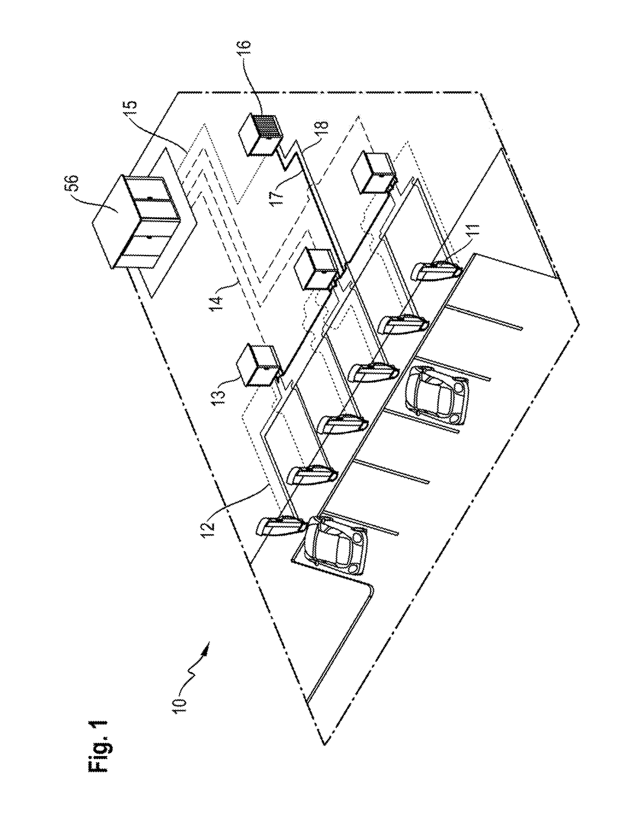
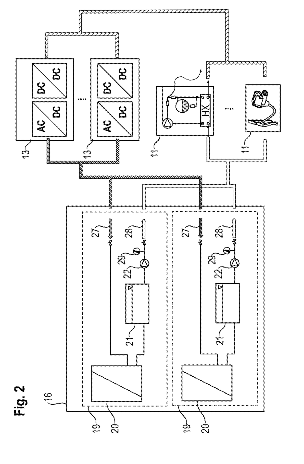
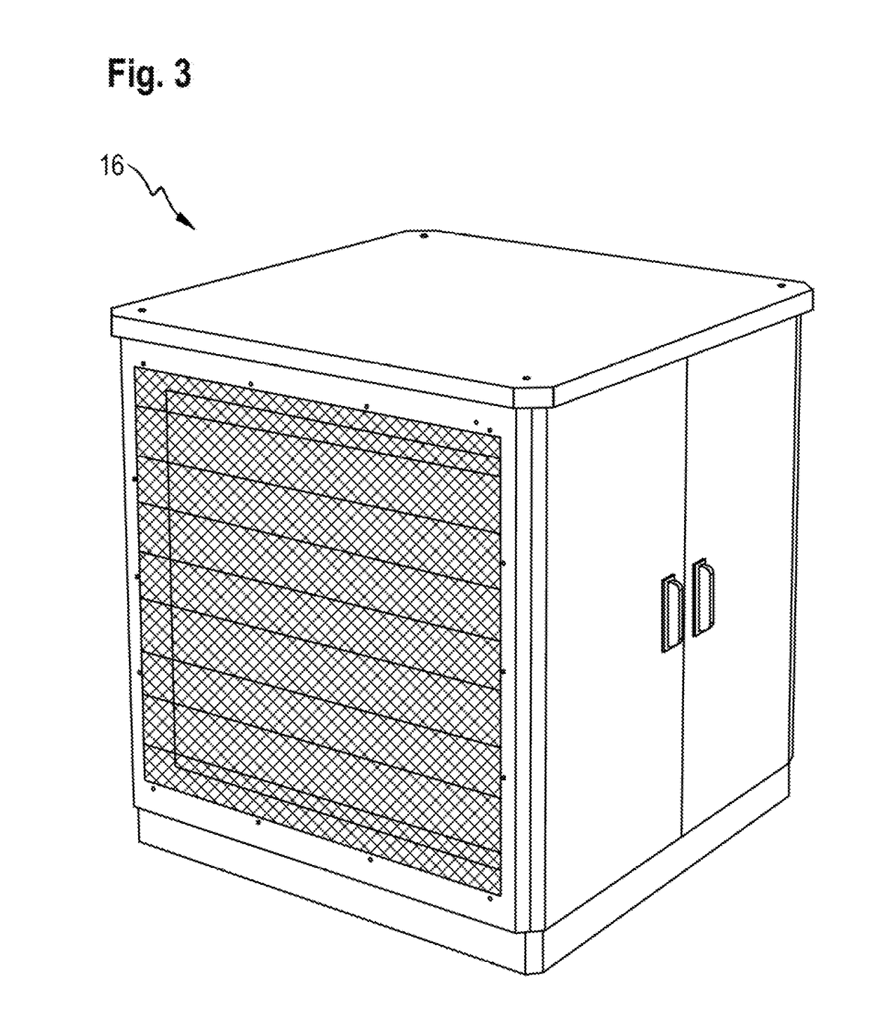
[0027]FIG. 1 illustrates the structure of an installation (10) according to aspects of the invention comprising charging columns (11), direct-current lines (12), rectifiers (13), three-phase alternating-current lines (14), a single-phase alternating-current line (15) and also a central cooling arrangement (16). The direct-current lines (12), which are designed for 800 V for example, in this case connect the charging columns (11) to the rectifiers (13) which, for their part—for example with a voltage of 480 V—are fed from a medium-voltage transformer (56) via the three-phase alternating-current lines (14) by switch panel. In addition, said medium-voltage transformer is, in turn, connected to the cooling arrangement (16) via a conventional single-phase alternating-current line (15) and supplies said cooling arrangement with a conventional domestic low voltage. In this case, the installation (10) comprises, in fluidic terms, a common primary cooling circuit (47) which connects the char...


PUM

PropertyMeasurementUnit
voltageaaaaaaaaaa
voltageaaaaaaaaaa
DC voltageaaaaaaaaaa

Abstract

An installation for charging electric cars includes the following features: charging columns, direct-current lines, rectifiers, three-phase alternating-current lines, a single-phase alternating-current line and a cooling arrangement. The direct-current lines electrically connect the charging columns to the rectifiers. The three-phase alternating-current lines electrically connect the rectifiers to a medium-voltage transformer. The single-phase alternating-current line electrically connects the medium-voltage transformer to the cooling arrangement.

Description

CROSS-REFERENCE TO RELATED APPLICATION[0001]This application claims priority to German Patent Application No. DE 10 2017 115 641.0, filed Jul. 12, 2017, which is incorporated by reference herein in its entirety.FIELD OF THE INVENTION[0002]The present invention relates to an installation for charging electric cars.BACKGROUND OF THE INVENTION[0003]In electrical engineering, a charging station is any stationary apparatus or electrical installation which serves to supply energy to mobile rechargeable battery-operated devices, machines or motor vehicles by simple placement or insertion, without the energy store—for example the traction battery of an electric car—having to be removed. Charging stations for electric cars are sometimes also called “electricity charging stations” and can comprise a plurality of charging points.[0004]In particular, high-performance direct-current charging systems such as the so-called combined charging system (CCS) which is widespread throughout Europe are kn...

Claims


Application Information

Patent Timeline
Patent Type & Authority Applications(United States)
IPC IPC(8): B60L11/18H01M10/613H01M10/625H01M10/667
CPCB60L11/1825H01M10/613B60L2230/10H01M10/625H01M10/667B60L11/1874H02J7/0027H02J7/0042H02J7/02H05K7/2089H05K7/20909H05K7/20927H01M10/48B60L53/31H01M10/6563H01M10/6568B60L53/67B60L53/51B60L53/302B60L53/305Y02T90/16Y02T10/7072Y02T10/70Y02T90/12Y02E60/10B60L58/26
Inventor GROMANUELREBER, VOLKERGOTZ, STEFAN
Owner DR ING H C F PORSCHE AG
Learn More