
Display device

a display device and display technology, applied in the direction of identification means, electrical apparatus casings/cabinets/drawers, instruments, etc., can solve the problems of difficult to achieve and maintain flatness of the display device, the display device may be vulnerable to external impact, etc., and achieve the effect of improving flatness

Active Publication Date: 2019-01-17
SAMSUNG DISPLAY CO LTD
View PDF5 Cites 14 Cited by
  • Summary
  • Abstract
  • Description
  • Claims
  • Application Information

AI Technical Summary

Benefits of technology

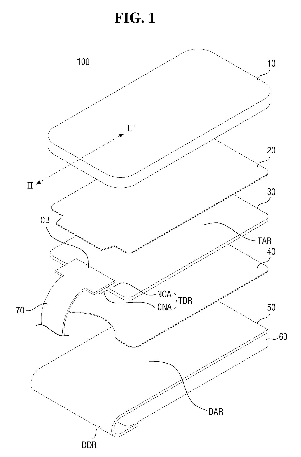
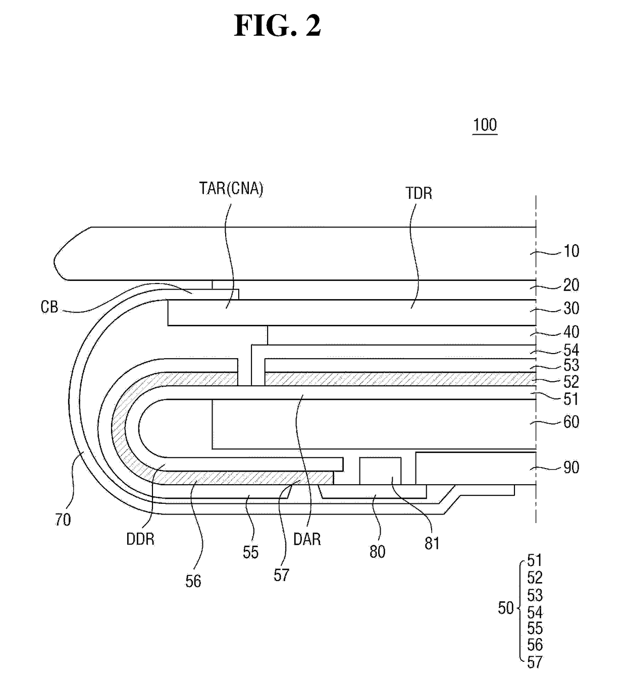
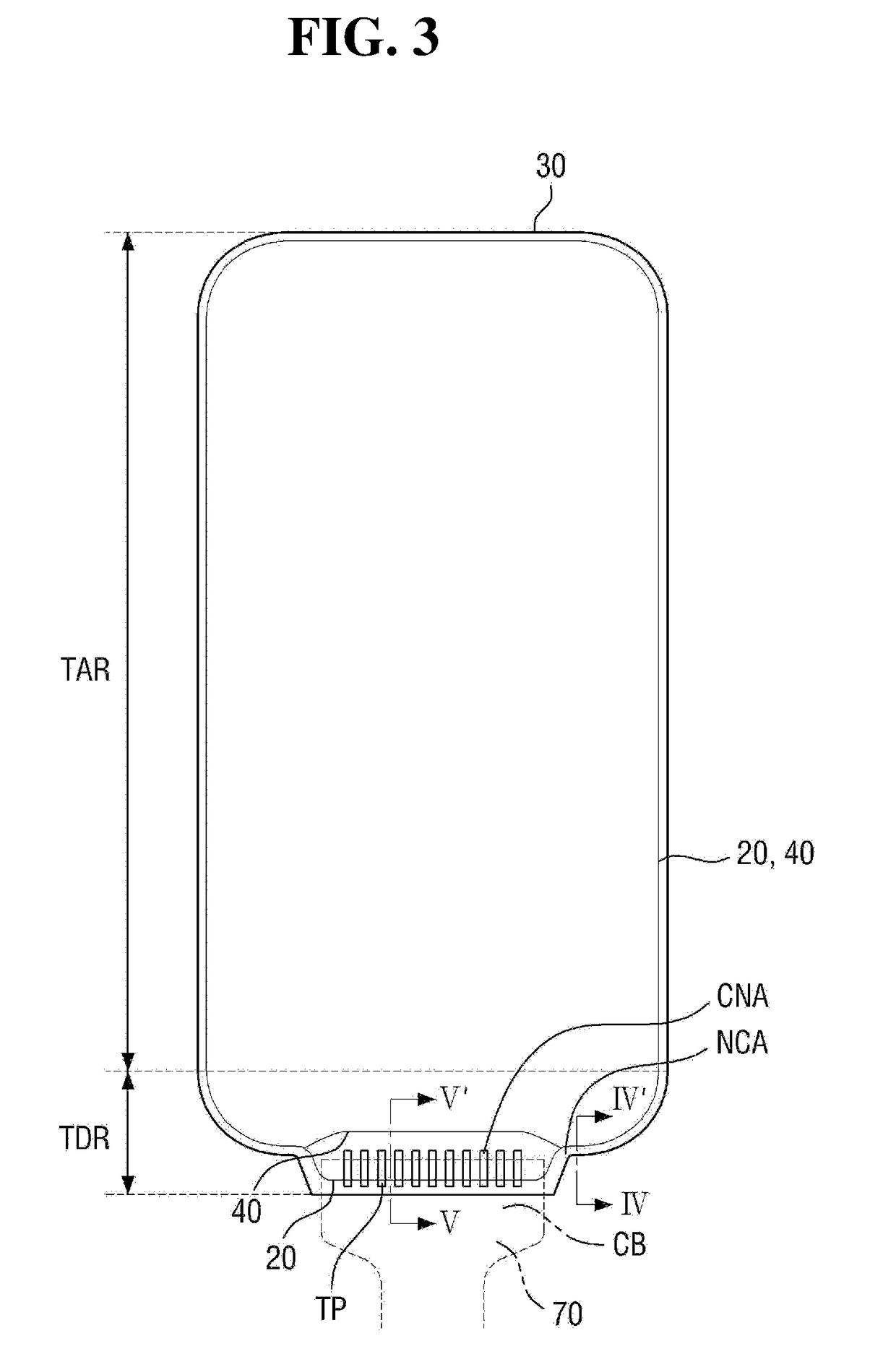
This patent describes a display device with improved flatness. The device includes a first optically transparent adhesive member that fills the space between the touch printed circuit board and the window, preventing the attachment portion of the touch printed circuit board from coming off and protecting the device from external impact. Additionally, a second optically transparent adhesive member that is concavely recessed on the connection area exposes the other surface of the touch panel, securing space for the attachment process of the touch printed circuit board and reducing the likelihood of external force or wrinkle transmission to the display panel located therebelow.

Problems solved by technology

If there is a stepped space at an end portion between the window, the touch panel, and the display panel that are attached to each other, the display device may be vulnerable to an external impact, and it may further be difficult to achieve and maintain flatness of the display device.

Method used


Image

  • Display device
  • Display device
  • Display device

Examples


Embodiment Construction

[0045]Features of the inventive concept and methods of accomplishing the same may be understood more readily by reference to the following detailed description of embodiments and the accompanying drawings. Hereinafter, embodiments will be described in more detail with reference to the accompanying drawings. The present invention, however, may be embodied in various different forms, and should not be construed as being limited to only the illustrated embodiments herein. Rather, these embodiments are provided as examples so that this disclosure will be thorough and complete, and will fully convey the aspects and features of the present invention to those skilled in the art. Accordingly, processes, elements, and techniques that are not necessary to those having ordinary skill in the art for a complete understanding of the aspects and features of the present invention may not be described. Unless otherwise noted, like reference numerals denote like elements throughout the attached drawi...


PUM


Abstract

A display device includes a first panel including a pad side area at one side of the first panel, a first optically transparent adhesive member on one surface of the first panel, a printed circuit board including a first attachment portion attached to the one surface of the first panel at the pad side area, a window on the first optically transparent adhesive member, a second optically transparent adhesive member on the other surface of the first panel, and a second panel on the second optically transparent adhesive member opposite the first panel, wherein the pad side area has a connection area at which the printed circuit board is attached to the first panel, and at which an edge of the first optically transparent adhesive member extends beyond an edge of the second optically transparent adhesive member, and a non-connection area at which the printed circuit board is not attached.

Description

CROSS-REFERENCE TO RELATED APPLICATION[0001]This application claims priority to, and the benefit of, Korean Patent Application No. 10-2017-0089891 filed on Jul. 14, 2017 in the Korean Intellectual Property Office, the disclosure of which is incorporated herein by reference in its entirety.BACKGROUND1. Field[0002]The present disclosure relates to a display device including a plurality of adhesion members and an adhesive member for bonding them.2. Description of the Related Art[0003]A display device is a device for displaying an image, and includes a display panel, such as an organic light-emitting display panel or a liquid crystal display panel. The display device may include a window for protecting the display panel from an external impact. In particular, the window is widely applied to portable electronic devices, such as smart phones. Some portable electronic devices have a touch input function. Such a display device may include a touch panel that performs a touch input function. ...

Claims


Application Information

Patent Timeline
IPC IPC(8): H01L27/32H05K1/14H05K5/00H01L51/52H05K1/11G06F3/044
CPCG06F3/044H05K2201/042H05K2201/056H05K2201/10128H05K2201/10151H05K2201/049H05K1/117H01L27/3276H05K1/147H05K5/0017H01L51/5246H01L27/323H05K2201/052G06F3/0412G09F9/00H10K59/873H10K59/8722H10K59/875G02F1/13338G02F1/13452G02F2202/28G06F3/0446G06F3/0443G06F3/04164Y02E10/549H10K59/40H10K59/131G06F3/041H10K77/111H10K50/8426
Inventor PARK, SOON SUNGKIM, JEONG JINAHN, SEONG SIK
Owner SAMSUNG DISPLAY CO LTD
Learn More