Supercharge Your Innovation With Domain-Expert AI Agents!

System for controlling positions of epb caliper and cable by using driving current and ripple

a technology of driving current and ripple, applied in the direction of braking systems, failure-safe aspects, braking components, etc., can solve the problems of inability to accurately control the position, increase the complexity of design, and increase so as to reduce the cost of the product, the effect of increasing the driving effect and reducing the weight of the epb actuator

Inactive Publication Date: 2019-01-24
ERAE AMS CO LTD
View PDF0 Cites 0 Cited by
  • Summary
  • Abstract
  • Description
  • Claims
  • Application Information

AI Technical Summary

Benefits of technology

The present invention allows for accurate measurement of the number of rotations of the EBP motor without using a magnet or linear Hall sensor. This results in a lighter EBP actuator, easier design, and reduced cost. The system also allows for precise control of the caliper and cable of the EBP, and provides stability in the driving of the EBP system.

Problems solved by technology

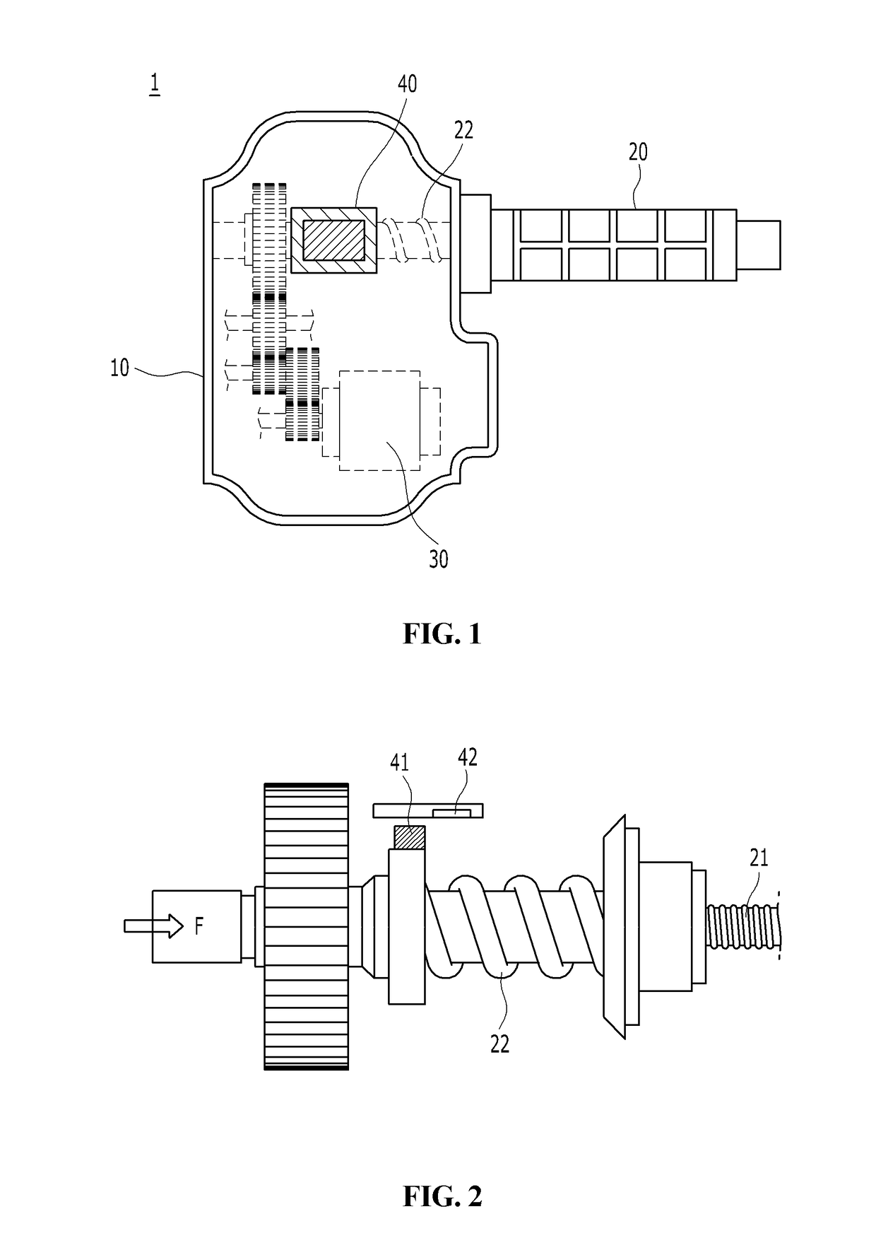
The material cost increases due to the addition of the magnet 41 and the linear Hall sensor assembly 42, and a magnetic body of the magnet 41 must have an optimized design to sensitively sense a change in the magnetic field, which results in increasing complexity of design.
In addition, if the magnetism is lost due to the characteristics of the magnet, the magnet cannot play the role of the sensor itself, which results in a phenomenon called brake drag, whereby there is a problem that accurate position control becomes impossible.
However, though reliability of the product can be increased in such a case, the material cost is further increased and the configuration of the EPB assembly is further complicated, whereby complexity of the apparatus design is increased.
In addition, according to such conventional device for controlling the positions of the caliper of the EPB having complicated configuration, there is also a risk that the driving of the motor or the actuator is not performed due to a subtle positional fluctuation caused by continuous use of the EPB, overheating of the motor, a sticking phenomenon due to foreign matter penetration into the actuator or abrasion phenomenon, and the like.

Method used


Image

  • System for controlling positions of epb caliper and cable by using driving current and ripple
  • System for controlling positions of epb caliper and cable by using driving current and ripple
  • System for controlling positions of epb caliper and cable by using driving current and ripple

Examples


Embodiment Construction

[0031]The embodiments described below are provided so that those skilled in the art can easily understand the technical idea of the present invention, and thus the present invention is not limited thereto. In addition, the matters described in the attached drawings may be different from those actually implemented by schematized drawings to easily describe embodiments of the present invention.

[0032]It is to be understood that when an element is referred to as being connected or connected to another element, it may be directly connected or connected to the other element, and other elements may be also present in between.

[0033]The term “connection” as used herein means a direct connection or an indirect connection between a member and another member, and may refer to all physical connections such as adhesion, attachment, fastening, bonding, and coupling.

[0034]The singular forms include plural forms unless the context clearly dictates otherwise. It is to be understood that the words “co...


PUM


Abstract

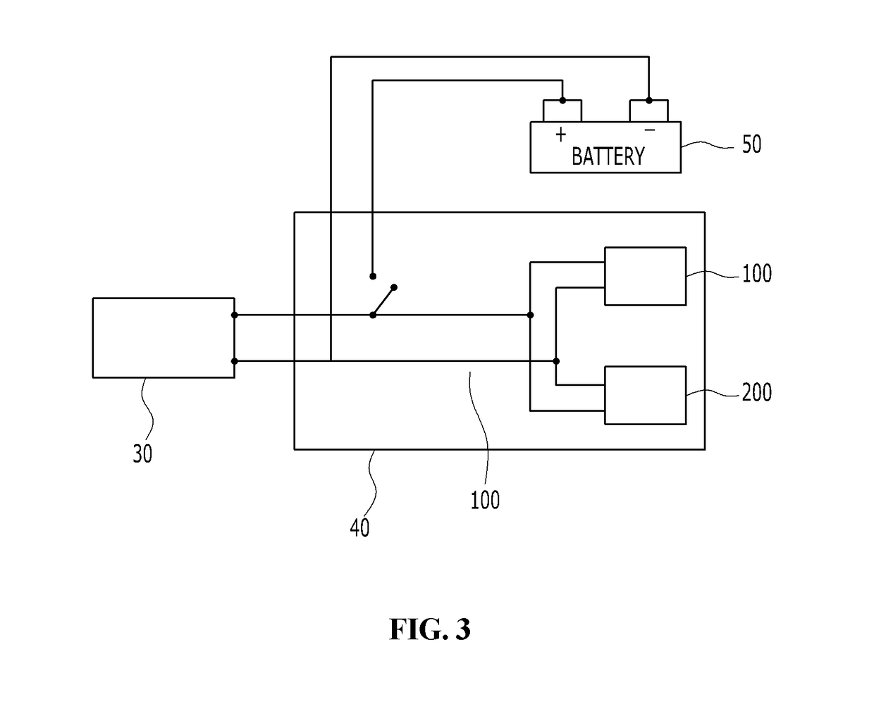
A system for controlling the positions of a caliper and a cable of an electric parking brake (EPB) includes: an actuator driving motor used for engaging and disengaging a parking brake of an EPB system; an electronic control module for controlling the motor; and a vehicle battery for supplying power to the motor and the electronic control module, wherein the electronic control module includes a ripple measuring unit for measuring the ripple of the motor by receiving an output signal of the motor and a current measuring unit for measuring a change in the driving current of the motor.

Description

BACKGROUND1. Technical Field[0001]The present invention relates to a system for controlling the positions of a caliper and a cable of an electric parking brake (EPB).2. Description of Related Art[0002]A parking brake of an automobile serves to brake rear wheels and / or front wheels of an automobile in order to maintain the state in which the automobile is stopped / parked. The parking brake is to prevent a vehicle from being unintentionally moved and functions in a manner whereby force is applied to the parking cable when a driver pulls the brake lever and the applied force is evenly distributed to the brake mechanism mounted on the wheel through the equalizer to cause the brake mechanism to restrain the wheel.[0003]An electric parking brake (EPB) is a brake system used as a substitute for a mechanical handle lever (side brake) or a foot pedal among parking brakes, in which the parking brake is enabled using simple button operation and motor power. In particular, the EPB can be linked ...

Claims


Application Information

Patent Timeline
Patent Type & Authority Applications(United States)
IPC IPC(8): B60R16/033B60T11/04B60T13/74B60T17/18B60T8/17B60T8/88F16D65/00H02P29/024
CPCB60R16/033B60T11/04B60T13/74B60T17/18B60T8/17B60T8/88F16D65/0068H02P29/024B60T7/10B60R16/03H02P29/0241B60T7/105B60T7/107B60T8/171B60T8/172B60T8/885B60T13/746F16D2066/003F16D2121/24B60T2270/40B60T13/662B60T2270/413F16D65/00
Inventor KANG, SHIN DEOKNOH, SEUNG SOOAHN, DAE KIKIM, DAE KYUNG
Owner ERAE AMS CO LTD
Features
  • R&D
  • Intellectual Property
  • Life Sciences
  • Materials
  • Tech Scout
  • Unparalleled Data Quality
  • Higher Quality Content
  • 60% Fewer Hallucinations
Learn More