In-vehicle processing device and in-vehicle system

a technology of in-vehicle processing and in-vehicle system, which is applied in the direction of power distribution line transmission, line-transmission details, baseband system details, etc., can solve problems such as failure in correct data transmission, and achieve the effect of suppressing data quality degradation and reducing power consumption

Active Publication Date: 2019-01-24
HITACHI ASTEMO LTD
View PDF6 Cites 2 Cited by
  • Summary
  • Abstract
  • Description
  • Claims
  • Application Information

AI Technical Summary

Benefits of technology

[0009]According to the present invention, it is possible to reduce power consumption while suppressing quality degradation of data to be transmitted and received. Problems, configurations, and effects other than in the above will become apparent by the following description in the embodiments as follows.

Problems solved by technology

This, however, would cause a problem of failure in correct data transmission due to effects of reflection generated when the communication speed is increased to 2 Mbps in a conventional network configuration enabling communication at 500 kbps.

Method used


Image

  • In-vehicle processing device and in-vehicle system
  • In-vehicle processing device and in-vehicle system

Examples


first embodiment

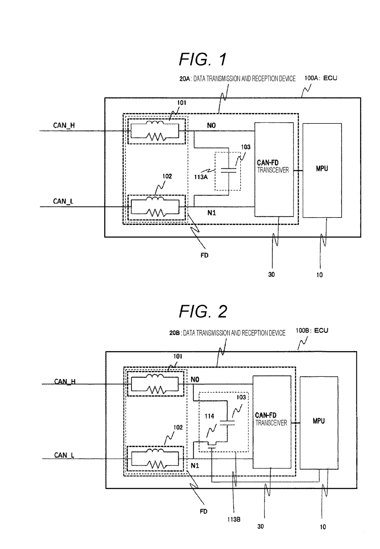
[0015]FIG. 1 illustrates a configuration of an ECU (100A) according to a first embodiment. A pair of CAN buses (CAN_H and CAN_L) is connected to the ECU (100A). The ECU (100A) is formed with a micro processing unit (MPU) 10 and a data transmission and reception device 20A.

[0016]In other words, the ECU 100A (in-vehicle processing device) includes the data transmission and reception device 20A that transmits and receives data and the MPU 10 (processor) that controls the data transmission and reception device 20A.

[0017]In the data transmission and reception device 20A, filter circuits (101 and 102) are respectively connected between the CAN bus (CAN_H and CAN_L) and internal nodes (N0 and N1). The internal nodes (N0 and N1) are connected to a CANFD transceiver 30 (CANFD driver).

[0018]In other words, the data transmission and reception device 20A includes the internal node NO (first communication line) and the internal node N1 (second communication line) constituting a differential tran...

second embodiment

[0030]FIG. 2 illustrates a configuration of an ECU (100B) according to a second embodiment. As compared with the first embodiment, a steady current suppression circuit 113B in the present embodiment further includes a switch 114.

[0031]That is, the steady current suppression circuit 113B in the second embodiment includes the switch 114 that is on / off controlled by the MPU between the capacitor 103 and either of the internal nodes N0 and N1. This switch 114 is in normally OFF state, with the steady current suppression circuit 113B not connecting the internal nodes N0 and N1, that is, the nodes are disconnected from each other. Under the control of the MPU 10, the switch 114 is turned on when the ECU 10 is in a transmission state with respect to the CAN bus, connecting the nodes (N0 and N1) with each other by the steady current suppression circuit 113B, so as to form a circuit equivalent to the circuit in the first embodiment.

[0032]In other words, the steady current suppression circuit...

third embodiment

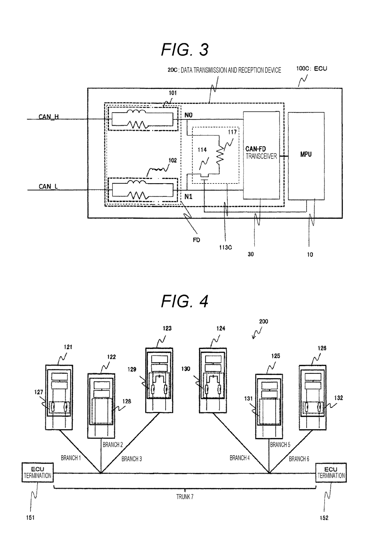
[0039]FIG. 3 illustrates a configuration of an ECU (100C) according to a third embodiment. The steady current suppression circuit 113C includes a resistor 117 and the switch 114. In other words, the steady current suppression circuit 113C corresponds to the steady current suppression circuit 113B illustrated in FIG. 2 in which the capacitor 103 is replaced with the resistor 117. Specifically, the steady current suppression circuit 113C includes the resistor 117 and the switch 114 (switch element) connected in series to the resistor 117.

[0040]The MPU 10 performs on / off control of the switch 114 similarly to the second embodiment. That is, the MPU 10 (processor) turns off the switch 114 (switch element) during a period in which the data transmission and reception device 20C receives data, while turns on the switch 114 during a period in which the data transmission and reception device 20C transmits data.

[0041]Since noise is generated when the ECU (100C) is in the transmission state, t...


PUM


Abstract

The present invention provides an in-vehicle processing device and an in-vehicle system capable of reducing power consumption while suppressing quality degradation of data to be transmitted and received. An ECU includes a data transmission and reception device for transmitting and receiving data and an MPU for controlling the data transmission and reception device. The data transmission and reception device includes a filter device and a steady current suppression circuit. The filter device attenuates noise that is superimposed on data by reflection of the data. The steady current suppression circuit suppresses a steady current flowing through the filter device and facilitates a transient current flowing through the filter device.

Description

TECHNICAL FIELD[0001]The present invention relates to an in-vehicle processing device and an in-vehicle system.BACKGROUND ART[0002]With the progress in safe driving support and automatic driving technology, the traffic of in-vehicle networks is increasing. In order to handle this, there is a known CAN with Flexible Data-rate (CAN FD) communication system capable of accelerating data transmission and data length extension. In the CAN FD, nodes that perform transmission and reception are typically electronic control units (ECU) as in-vehicle processing devices, and each of the nodes is electrically connected with each other by a bus. A transmission ECU adds an identifier (ID) to communication data to form a message, converts the message into an electric signal to be transmitted onto the bus. Each of the ECUs monitors electric signals on the bus, obtains the ID being used for communication, and identifies the message to be received.[0003]In a case where a plurality of messages is simul...

Claims


Application Information

Patent Timeline
Patent Type & Authority Applications(United States)
IPC IPC(8): H04L25/02H04B1/10B60R16/023H04B3/56
CPCB60R16/023H04B3/02H04L25/02H04B1/10H04B1/40H04B3/56H04B2203/5491H04L25/029H04L25/0292
Inventor SORAKU, KOICHIOSADA, KENICHI
Owner HITACHI ASTEMO LTD
Why Eureka
Try Eureka