Switching power supply having active power factor correction

a technology of switching power supply and power factor correction, which is applied in the direction of power supply for data processing, liquid/fluent solid measurement, instruments, etc., can solve the problems of limiting the use of switching power supply, affecting the service life of low and high-temperature electrolytic capacitors, and becoming a difficult thing to use switching power supply, etc., to achieve low loss, simple wiring, and low cost.

Active Publication Date: 2019-01-24
MORNSUN GUANGZHOU SCI & TECH
View PDF8 Cites 10 Cited by
  • Summary
  • Abstract
  • Description
  • Claims
  • Application Information

AI Technical Summary

Benefits of technology

[0032]The cost is extremely low, and the additionally arranged indicating circuit is low in loss, which nearly has no influence on the efficiency of the original switching power supply having the active power factor correction. The switching power supply is simple in wiring, small in volume and convenient to use. Moreover, co...

Problems solved by technology

Because of the use of the electrolytic capacitor C101, its characteristics limit the use of the switching power supply.
It has been always an industrial problem to prolong the low and high-temperature service lives of the electrolytic capacitor.
That is to say, under an environment with a temperature of −40 degrees celsius, such as three provinces in the northeast of China, Xinjiang, and countries and regions at high latitudes, it becomes a tough thing to use the switching power supply.
Of course, a CBB thin film capacitor may be used for filtering, but it is extremely large in volume and extremely high in cost.
For the switching power supply adopting the BUCK power factor correction circuit, the BUCK PFC has a low output voltage, so that the PFC electrolytic capacitor for filtering is required to bear higher ripple current, and the problem on the service life of the PFC electrolytic capacitor cannot be ignored either.
Of course, there is another kind of power factor correction circuit taking BUCK-BOOST as its main topology, which may realize voltage drop and voltage r...

Method used


Image

  • Switching power supply having active power factor correction
  • Switching power supply having active power factor correction
  • Switching power supply having active power factor correction

Examples


first embodiment

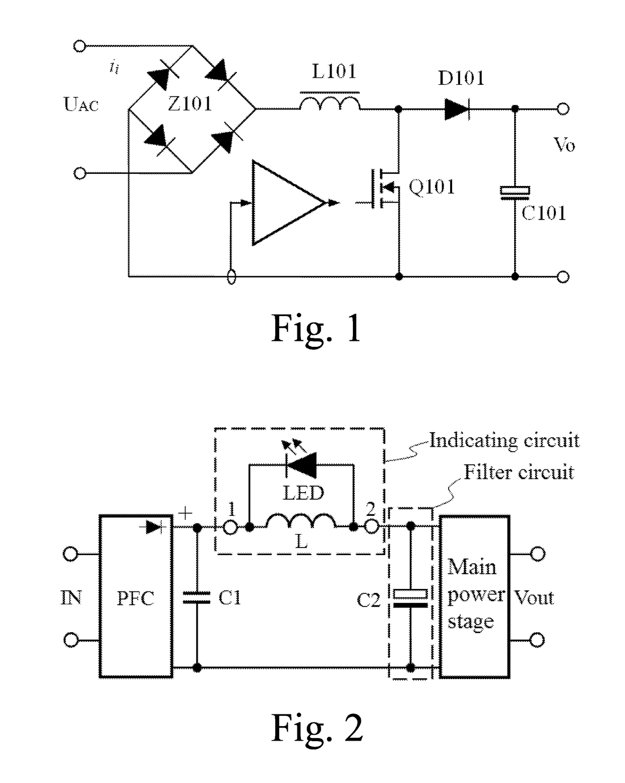
[0055]FIG. 2 shows a schematic diagram of a switching power supply having active power factor correction of a first embodiment of the present application. The switching power supply comprises a power factor correction circuit PFC, a filter circuit, a main power stage, a first capacitor C1 and an indicating circuit having two terminals 1 and 2. An alternating current input IN is connected to the first capacitor C1 through the power factor correction circuit PFC, and then is connected to the filter circuit through the indicating circuit; the filter circuit is connected in parallel with the main power stage; the filter circuit at least comprises a second capacitor C2 used as an electrolytic capacitor; and the indicating circuit is formed by connecting a light emitting unit having unidirectional conductivity to a first inductor L in parallel, and makes sure that the current direction of power supplied from the power factor correction circuit PFC to the main power stage through the first...

second embodiment

[0090]The second embodiment is as shown in FIG. 10, which shows a schematic diagram of a switching power supply having active power factor correction of the second embodiment of the present application. The switching power supply comprises a power factor correction circuit PFC, a filter circuit, a main power stage, a first capacitor C1 and an indicating circuit having two terminals 1 and 2. An alternating current input IN is connected to the first capacitor C1 through the power factor correction circuit PFC, and then is connected to the filter circuit through the indicating circuit; the filter circuit is connected in parallel with the main power stage; the filter circuit at least comprises a second capacitor C2 used as an electrolytic capacitor; and the indicating circuit is formed by connecting a light emitting unit having unidirectional conductivity to a first inductor L in parallel, and makes sure that the current direction of power supplied from the power factor correction circu...

third embodiment

[0101]Referring to FIG. 11, it is a schematic diagram of an indicating circuit in the third embodiment of the present application. A light emitting unit is formed by connecting a light emitting diode LED and a first diode D in series in the same direction. A connection relation of the indicating circuit is as follows: the first diode D and the first light emitting diode are connected in series in the same direction to form a two-terminal network which is connected in parallel with an inductor L; a connection point of the cathode of the two-terminal network and the first inductor forms a first terminal 1; and a connection point of the anode of the two-terminal network and the first inductor forms a second terminal 2.

[0102]The two-terminal network is: a circuit structure which is formed by interconnecting one or two or more elements and has two terminals.

[0103]The anode and the cathode of the two-terminal network are as follows: for the two-terminal network having unidirectional condu...


PUM


Abstract

A switch power supply having active power factor correction is provided, including a power factor correction (PFC) circuit, a filter circuit, a main power stage, a first capacitor (C1) and an indicating circuit. An alternating-current input (IN) is connected to the first capacitor through the PFC circuit and is connected to the filter circuit through the indicating circuit. The indicating circuit consists of a light emitting diode (LED) having unidirectional conductivity and an inductor (L); and the current direction of power supplied from the PFC circuit to the main power stage through the inductor is opposite to the conduction direction of the LED. The LED may also be a light emitter of a photocoupler. The filter circuit at least comprises an electrolytic capacitor (C2). When the electrolytic capacitor is normal, an exciting current of the main power stage basically does not appear in the inductor and the LED does not emit light. When the equivalent series resistance (ESR) of the electrolytic capacitor sharply rises, the exciting current appears in the inductor. When a power transistor in the main power stage is switched off, the exciting current in the inductor cannot be abruptly changed; instead, the exciting current passes through the LED for freewheeling and enables the LED to emit light, thereby notifying a user or a circuit that the electrolytic capacitor may have the risk of failure. The switch power supply has low additional cost and unchanged efficiency and is easy to implement.

Description

TECHNICAL FIELD[0001]The present application relates to the field of switching power supplies, and more particularly relates to a high-reliability switching power supply having active power factor correction, which converts alternating current or direct current into direct current.DESCRIPTION OF RELATED ART[0002]At the present, switching power supplies have a wide range of applications. Fly-back switching power supplies have a wide range of applications to occasions where input power is less than 75 W and have no requirements on Power Factors (PF). For power supplies having the input power more than 75 W, even many switching power supply type drivers for illumination, even though the power less than 75 W, have requirements on their power factors according to the national standard.[0003]Currently, a power factor correction circuit has been adopted to solve this problem. The power factor correction circuit is called PFC (Power Factor Correction) circuit for short. A low-cost method is...

Claims


Application Information

Patent Timeline
IPC IPC(8): H05B33/08H02M1/42G06F1/26H01F27/30H05B44/00
CPCH02M1/42H02M3/335H02M7/217H02M3/33571H02M1/4225H02M3/01H02M1/32H02M1/4266G06F1/263Y02B70/10H05B45/39H05B45/3725H05B45/385H02M1/0064H02M1/0058H02M1/007H01F27/30H02M1/4208
Inventor WANG, BAOJUN
Owner MORNSUN GUANGZHOU SCI & TECH
Why Eureka
Try Eureka