Infrared denaturing device

a denaturing device and infrared technology, applied in the field of infrared denaturing devices, can solve the problems of malignant cells carbonization (blackening) denaturation, etc., and achieve the effect of optimal shape, long time for surgery, and efficient coagulation of biological tissu

Active Publication Date: 2019-01-31
KYORIN UNIVERSITY
View PDF0 Cites 1 Cited by
  • Summary
  • Abstract
  • Description
  • Claims
  • Application Information

AI Technical Summary

Benefits of technology

[0011]An improvement required for the second-generation coagulator is that since the shape of the light emitting end surface of the tip probe is a 10-mm circle, and the light emitting surface is small for use in a human, requiring multiple times of radiation for linear or belt-like irradiation and thus taking a long time for the surgery. Therefore, in order to realize efficient coagulation of the biological tissue such as the myocardium, the present invention has an objective of providing an infrared denaturing device having a light emitting surface with a more optimal shape.
[0012]In order to perform interruptive blocking of the abnormal conductive pathway by tissue coagulation of the myocardial tissue from the epicardium side, a device that can control the size and the depth of the coagulation is required. However, a device that is capable of forming a transmural coagulation in a length generally extending 30 millimeters or deep in the depth direction of the atrial wall has a problem of carbonization (blackening) denaturation resulting from a histological reaction of the surface layer, and thus is unavailable under the present circumstances. In addition, since coagulation may be performed on the beating heart using a myocardial thoracoscope or the like, stable handling of the light emitting end surface in a narrow operational field and a function of ensuring blocking of the supposed area with one shot are also required.

Problems solved by technology

An improvement required for the second-generation coagulator is that since the shape of the light emitting end surface of the tip probe is a 10-mm circle, and the light emitting surface is small for use in a human, requiring multiple times of radiation for linear or belt-like irradiation and thus taking a long time for the surgery.
However, a device that is capable of forming a transmural coagulation in a length generally extending 30 millimeters or deep in the depth direction of the atrial wall has a problem of carbonization (blackening) denaturation resulting from a histological reaction of the surface layer, and thus is unavailable under the present circumstances.
Even if coagulation is repeatedly performed on the surface layer of the myocardial tissue with a coagulator so as to visually cover the entire targeted area, interruptive blocking of the abnormal conductive pathway, a sterilization treatment against the bacterial layer and coagulation procedure for malignant cells intended would be incomplete if continuity of the coagulation is disturbed underneath the surface layer of the myocardial tissue.

Method used


Image

  • Infrared denaturing device
  • Infrared denaturing device
  • Infrared denaturing device

Examples


first embodiment

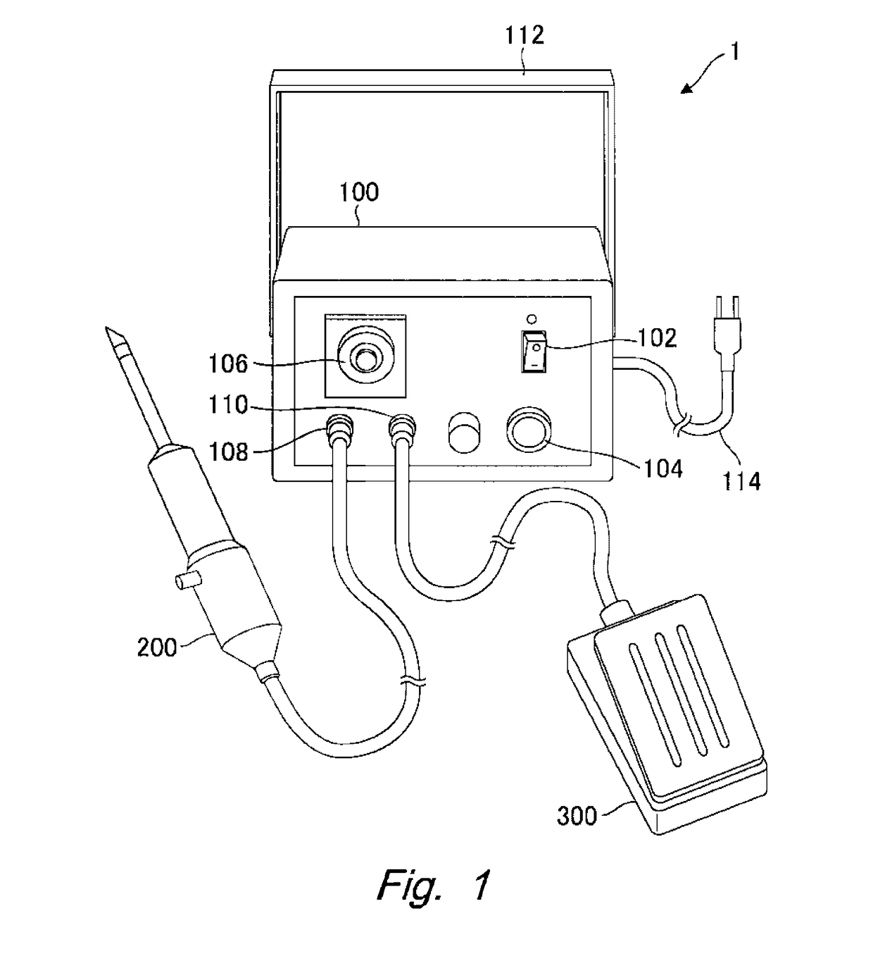
[0046]An infrared denaturing device according to a first embodiment of the present invention will be described with reference to FIGS. 1-5. An infrared denaturing device 1 shown in FIG. 1 is provided with a device body 100 equipped with various switches, a handheld equipment 200 for emitting infrared light, and a foot switch 300 for controlling infrared radiation. The device body 100 is provided with a power switch 102 for turning the power source on and off, an infrared radiation switch 104 for controlling infrared radiation, a timer 106 for setting infrared radiation time, a handheld equipment connector 108 connected to a cable of the handheld equipment 200, a foot switch connector 110 connected to a cable of the foot switch 300, a handle 112 rotatably attached to the device body 100, and a power cord 114 connected to an external power supply.

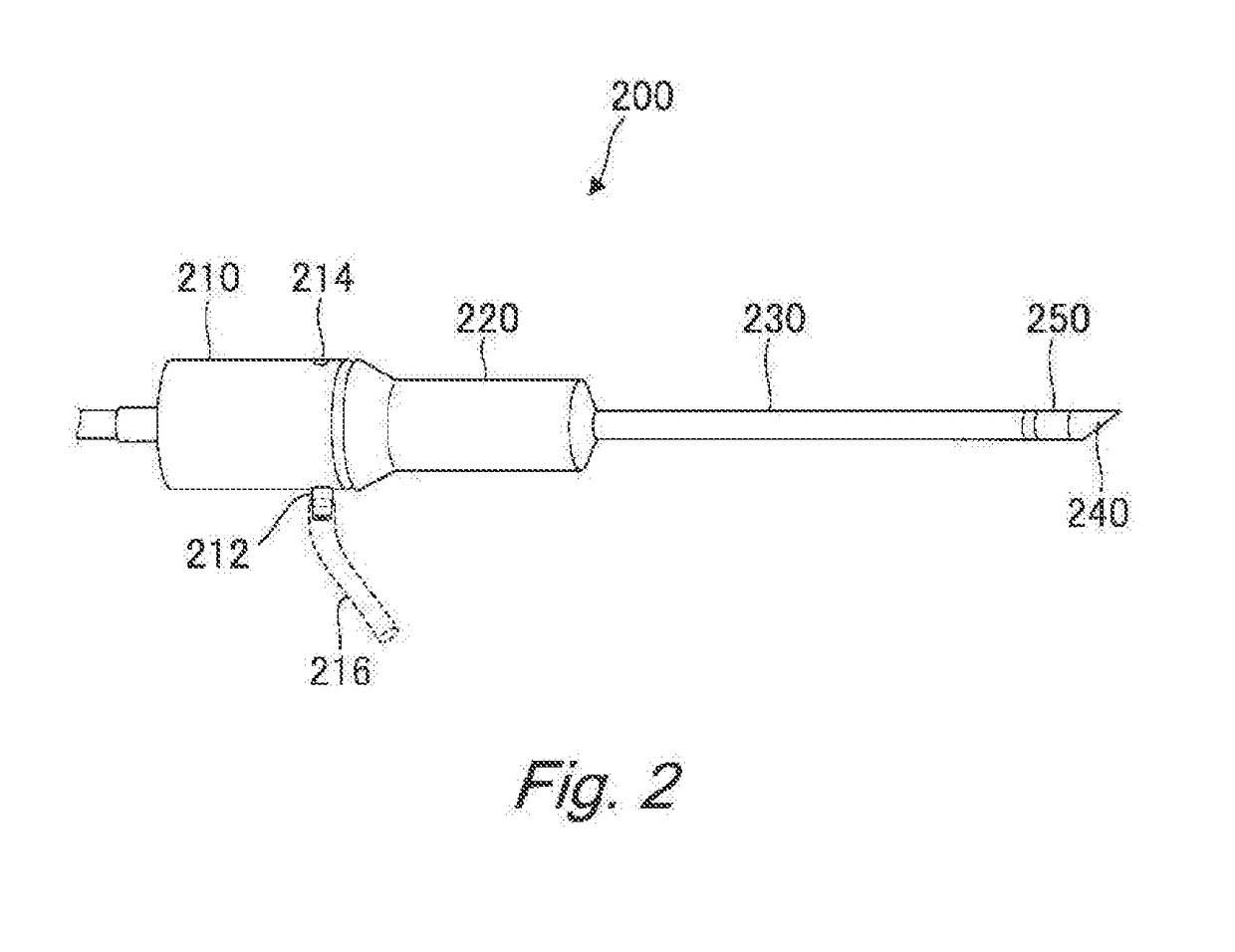
[0047]The handheld equipment 200 shown in FIG. 2 is provided with a hollow body part (lamp house) 210 for accommodating an infrared lamp, a ...

second embodiment

[0057]An infrared denaturing device according to a second embodiment of the present invention will be described with reference to FIG. 6. The infrared denaturing device according to the second embodiment differs from the infrared denaturing device of the first embodiment in the shapes of the light projecting body and the guard guide. In FIG. 6A is a side view of a light projecting body 240A, 6B is a front view of the light projecting body 240A seen from its tip, 6C is a side view of the light projecting body 240A attached with a guard guide 260A, and 6D is a front view of the light projecting body 240A in the state of 6C seen from its tip.

[0058]As shown in FIG. 6A, the light projecting body 240A is generally columnar with a round light emitting end, which is preferably shaped into a hemisphere or a dome. Furthermore, as shown in FIGS. 6A and 6B, a recess cut into a conical shape is formed in the center of the round light emitting end of the light projecting body 240, where this rece...

third embodiment

[0059]An infrared denaturing device according to a third embodiment of the present invention will be described with reference to FIG. 7. The infrared denaturing device according to the third embodiment differs from the infrared denaturing device according to the first embodiment in the shapes of the light projecting body and the guard guide. In FIG. 7A is a top view of a light projecting body 240B, 7B is a side view of the light projecting body 240B, 7C is a front view of the light projecting body 240B in the state of 7B seen from its tip, 7D is a side view of the light projecting body 240B attached with a protection guard 260B, and 7E is a front view of the light projecting body 240B in the state of 7D seen from its tip.

[0060]As shown in FIGS. 7A-7C, the light projecting body 240B is a substantially columnar rod where the sides of the tip are cut off to form a pair of reflecting surfaces 242B. A tapered cut angle γ is formed between the reflecting surfaces 242B. This angle γ may be...


PUM


Abstract

The infrared denaturing device of the present invention is provided with: an infrared lamp which emits infrared light; a light guide which guides the infrared light; and a light projecting body which radiates the infrared light guided from the light guide onto an object to be denatured. The light projecting body is provided with: a reflecting surface which reflects the infrared light; and a radiating surface which radiates the infrared light reflected by the reflecting surface onto an object to be irradiated. Further, there is also provided a denaturing detection sensor which detects denaturing, by means of the infrared light, of a region being denatured.

Description

CROSS-REFERENCE TO RELATED APPLICATIONS[0001]This is a U.S. national phase application under 35 U.S.C. § 371 of International Patent Application No. PCT / JP2017 / 000283, filed Jan. 6, 2017, and claims benefit of priority to Japanese Patent Application No. 2016-001471, filed Jan. 7, 2016. The entire contents of these applications are hereby incorporated by reference.FIELD OF TECHNOLOGY[0002]The present invention relates to an infrared denaturing device used for surgical operations, and more particularly, to an infrared denaturing device (infrared coagulator) for carrying out atrial coagulation upon a surgical treatment for atrial fibrillation.BACKGROUND[0003]Surgical treatments for atrial fibrillation (MAZE surgery) are widely carried out in general, where various atrium coagulators have been developed for shortening the operation time to replace the operation of cutting and suturing the atrium by the so-called original cut-and-sew method. Radiofrequency (RF), cryothermy, microwave, ul...

Claims


Application Information

Patent Timeline
Patent Type & Authority Applications(United States)
IPC IPC(8): A61B18/18A61N5/06
CPCA61B18/18A61N5/06A61B2018/1807A61B2018/00589A61N2005/0659A61N2005/0666A61B2018/00839A61B2018/00648A61B2017/00199A61B2018/00791A61B2018/00363A61B2017/00973A61N2005/0654A61N5/0601A61B2017/00026A61B2018/00875A61B2017/00022A61B2018/00708A61B2018/00738A61B2018/00821A61B18/201A61B2017/00128A61B2018/00017A61B2018/00351A61B2018/00642A61B2018/2005A61B2018/20553
Inventor KUBOTA, HIROSHIHOSHINO, MASAHIKO
Owner KYORIN UNIVERSITY
Why Eureka
Try Eureka