Cu-BASED SINTERED SLIDING MATERIAL, AND PRODUCTION METHOD THEREFOR

a technology of cu-based sintered sliding material and production method, which is applied in the direction of sliding contact bearings, mechanical equipment, transportation and packaging, etc., can solve the problems of high cost of rolling bearings, achieve good yield, reduce the rate of dimensional change, and improve the wear characteristics of sliding

Active Publication Date: 2019-01-31
DIAMET CORP
View PDF2 Cites 0 Cited by
  • Summary
  • Abstract
  • Description
  • Claims
  • Application Information

AI Technical Summary

Benefits of technology

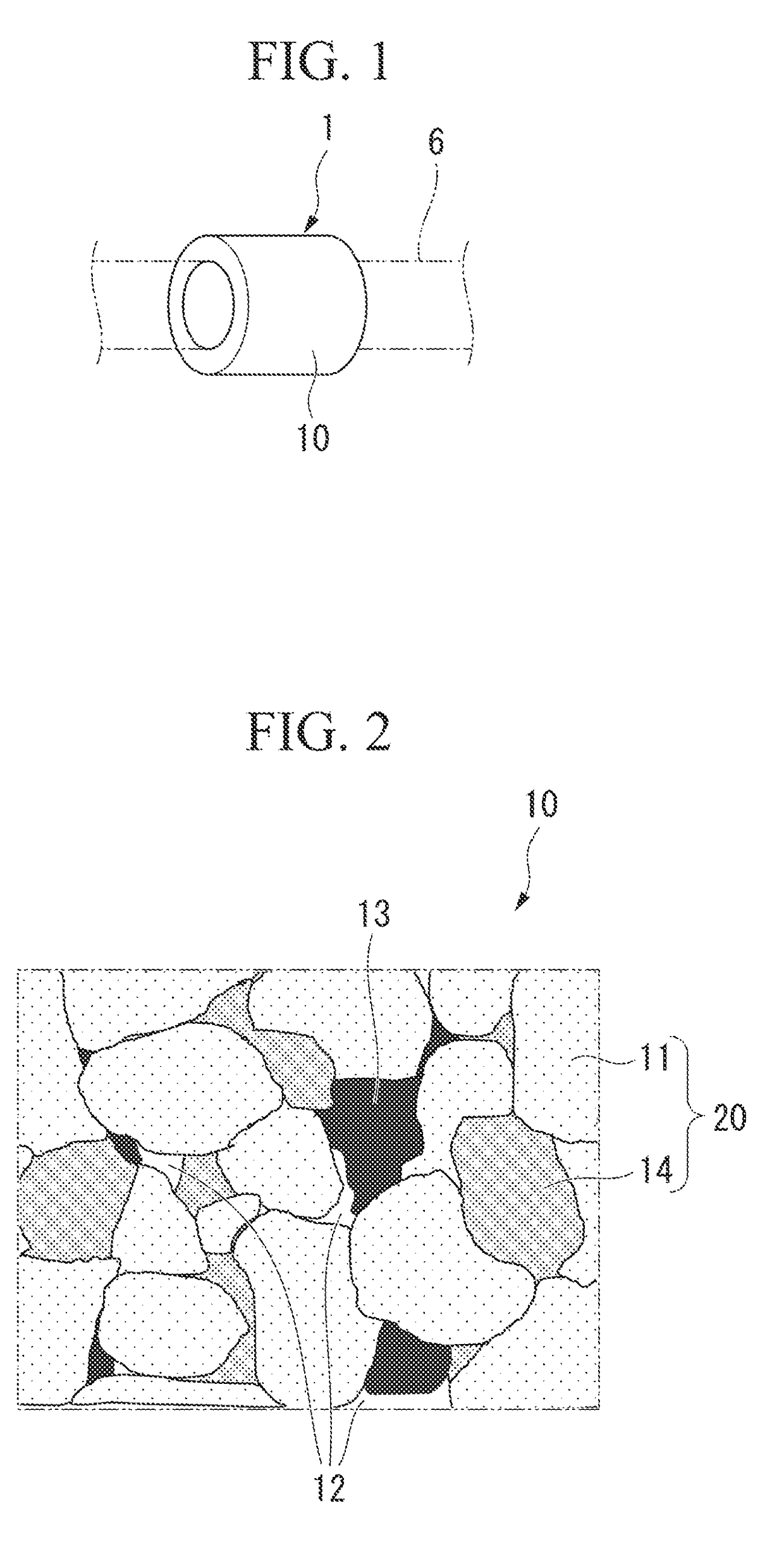
[0012]The Cu-based sintered sliding material of the present invention is a sintered material obtained by sintering Cu-Ni-based alloy grains, and wear characteristics during sliding are improved by including grain boundary phases containing Ni and P as main components. Furthermore, in the Cu-based sintered sliding material of the present invention, an amount of C in the metal matrix including (consisting of) the alloy grains and the grain boundary phases is suppressed to an appropriate value. Thus, it is possible to reduce the rate of dimensional change before and after sintering. That is, according to the present invention, it is possible to provide a sintered sliding material which hardly causes a large dimensional change such as abnormal expansion or shrinkage before and after sintering, and it can be produced with good yield. Furthermore, according to the present invention, by controlling the amount of Ni, the amount of Sn, and the amount of P contained in the metal matrix including (consisting of) the alloy grains and the grain boundary phases to be in suitable ranges, it is possible to provide a sintered sliding material that is excellent in strength and wear resistance, and is usable under a high rotation rate and a high surface pressure.

Problems solved by technology

However, since the rolling bearing is expensive, development of a sliding bearing that consists of a sintered member and is usable under a condition of a high surface pressure or a high rotation rate is expected.

Method used


Image

  • Cu-BASED SINTERED SLIDING MATERIAL, AND PRODUCTION METHOD THEREFOR

Examples


examples

[0070]Hereinafter, the present invention will be described in more detail with reference to examples, but the present invention is not limited to these examples.

[0071]

[0072]First, as raw material powders, several types of Cu—Ni alloy powders and Cu—Ni—Sn alloy powders which have different amounts of Ni, a Sn powder, a Cu-8%P alloy powder, a Ni-11%P alloy powder, and a graphite powder were prepared.

[0073]These raw material powders were blended as shown in Table 1 so as to obtain a final component composition as shown in Table 2 below, and 0.5% of zinc stearate was added. The mixture was mixed by a V type mixer for 20 minutes, and then the thus obtained mixed powder was press-molded to produce a green compact. In Table 1, powders which were not blended are indicated by “-”.

[0074]Next, this green compact was sintered at a predetermined temperature in a range of 760° C. to 900° C. in an endothermic gas atmosphere to obtain a sintered sliding material (Cu-based sintered sliding material)...


PUM

PropertyMeasurementUnit
porosityaaaaaaaaaa
temperatureaaaaaaaaaa
surface pressureaaaaaaaaaa

Abstract

The Cu-based sintered sliding material has a composition including, by mass %, 7% to 35% of Ni, 1% to 10% of Sn, 0.9% to 3% of P, and 0.5% to 5% of C, with a remainder of Cu and inevitable impurities, wherein the Cu-based sintered sliding material includes a sintered body including: alloy grains that contain Sn and C and contain a Cu-Ni-based alloy as a main component; grain boundary phases that contain Ni and P as main components and are dispersedly distributed in grain boundaries of the alloy grains; and free graphite that intervenes at the grain boundaries of the alloy grains, the Cu-based sintered sliding material has a structure in which pores are dispersedly formed in the grain boundaries of the alloy grains, and an amount of C in a metal matrix including the alloy grains and the grain boundary phases is, by mass %, 0.02% to 0.20%.

Description

CROSS-REFERENCE TO RELATED PATENT APPLICATIONS[0001]This application is a U.S. National Phase Application under 35 U.S.C. § 371 of International Patent Application No. PCT / JP2017 / 006343, filed Feb. 12, 2017, and claims the benefit of Japanese Patent Application No. 2016-042776, filed on Mar. 4, 2016, all of which are incorporated herein by reference in their entirety. The International Application was published in Japanese on Sep. 8, 2017 as International Publication No. WO / 2017 / 150271 under PCT Article 21(2).FIELD OF THE INVENTION[0002]The present invention relates to a Cu-based sintered sliding material, and a production method therefor.BACKGROUND OF THE INVENTION[0003]In general, a rolling bearing is adopted as a bearing used under a condition of a high surface pressure or a high rotation rate. However, since the rolling bearing is expensive, development of a sliding bearing that consists of a sintered member and is usable under a condition of a high surface pressure or a high ro...

Claims


Application Information

Patent Timeline
Patent Type & Authority Applications(United States)
IPC IPC(8): C22C9/06B22F3/11B22F5/00F16C17/10B22F1/105
CPCC22C9/06B22F3/11B22F5/00F16C17/10B22F2301/10F16C2204/10F16C17/02F16C33/10F16C33/12F16C33/14B22F5/106C22C1/0425B22F2998/10C22C9/02F16C33/104F16C33/128F16C33/121B22F1/105B22F9/04B22F3/02B22F3/10B22F2003/166
Inventor ISHII, YOSHINARI
Owner DIAMET CORP
Why Eureka
Try Eureka