Rotor blade of a wind turbine and a wind turbine

a technology of wind turbines and rotor blades, which is applied in the direction of wind energy generation, mechanical equipment, machines/engines, etc., can solve the problems of limited extent, inability to realize clean flow states, and inability to achieve clean flow states

Active Publication Date: 2019-01-31
WOBBEN PROPERTIES GMBH
View PDF0 Cites 8 Cited by
  • Summary
  • Abstract
  • Description
  • Claims
  • Application Information

AI Technical Summary

Benefits of technology

[0053]It has also been found that, with these abovementioned refinements, it is preferably possible to realize a rotor blade which has a glide ratio (lift/drag ratio) which, at angles of attack (twist) of up to 5°, lie above 1 and below 10, and in p

Problems solved by technology

Owing to the natural laws of aerodynamics and structural mechanics, however, it is not possible, or is possible only to a limited extent, to increase only the length of the rotor blades and, for example

Method used


Image

  • Rotor blade of a wind turbine and a wind turbine
  • Rotor blade of a wind turbine and a wind turbine
  • Rotor blade of a wind turbine and a wind turbine

Examples


Embodiment Construction

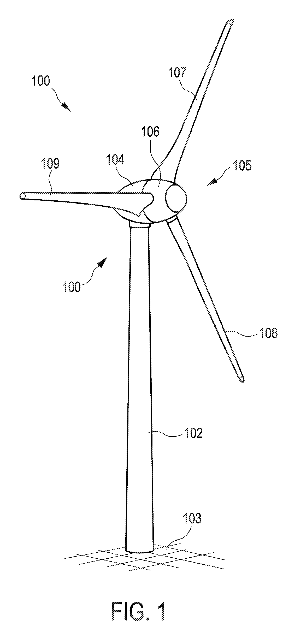
[0067]FIG. 1 shows a wind power installation 100 having a tower 102 which is erected on a foundation 103. At the upper end situated opposite the foundation 103, there is situated a nacelle 104 (machine housing) with a rotor 105, which has a rotor hub 106 and rotor blades 107, 108 and 109 attached thereto. The rotor 105 is coupled to an electrical generator in the interior of the nacelle 104 for the purposes of converting mechanical work into electrical energy. The nacelle 104 is mounted rotatably on the tower 102, the foundation of which 103 provides the required stability.

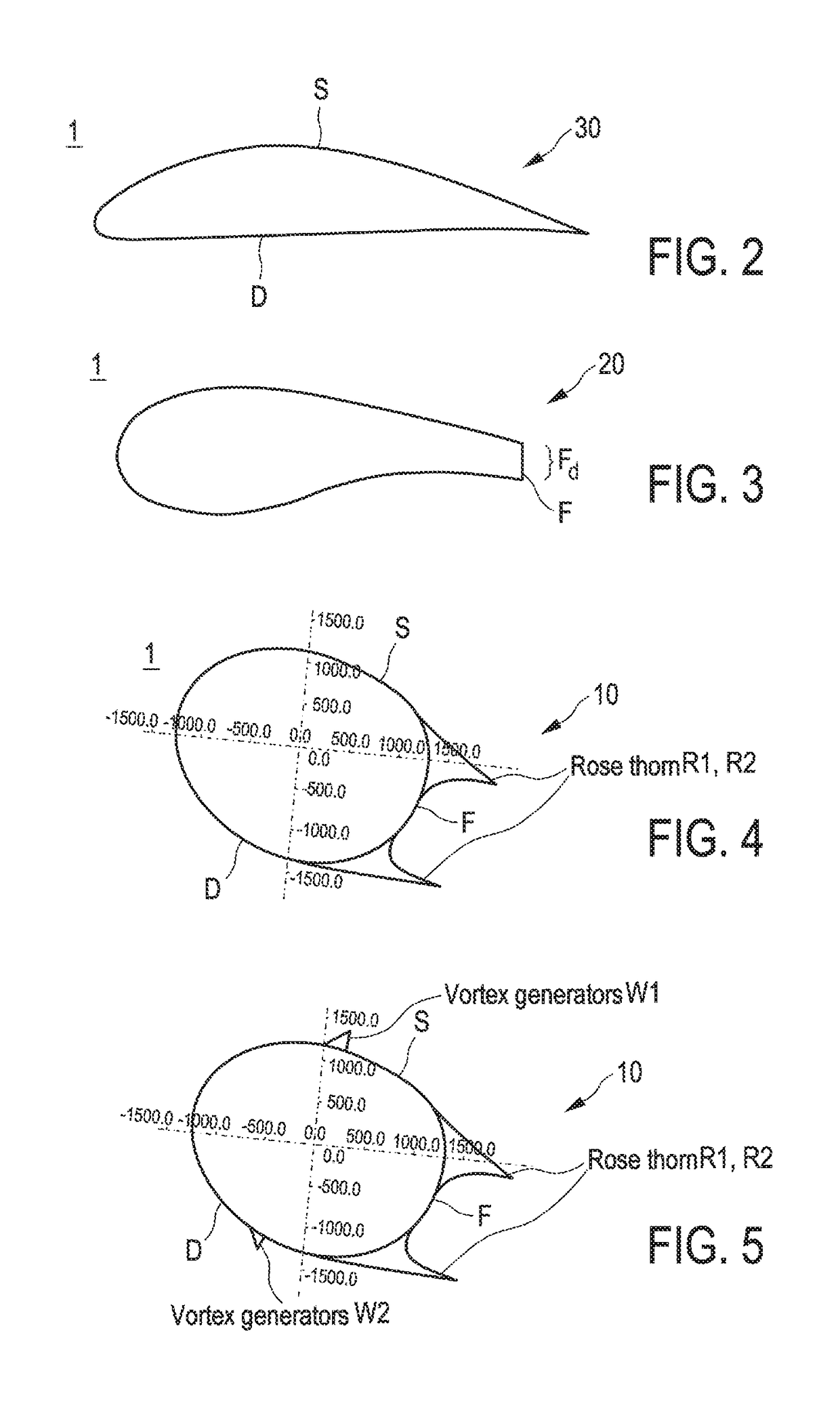
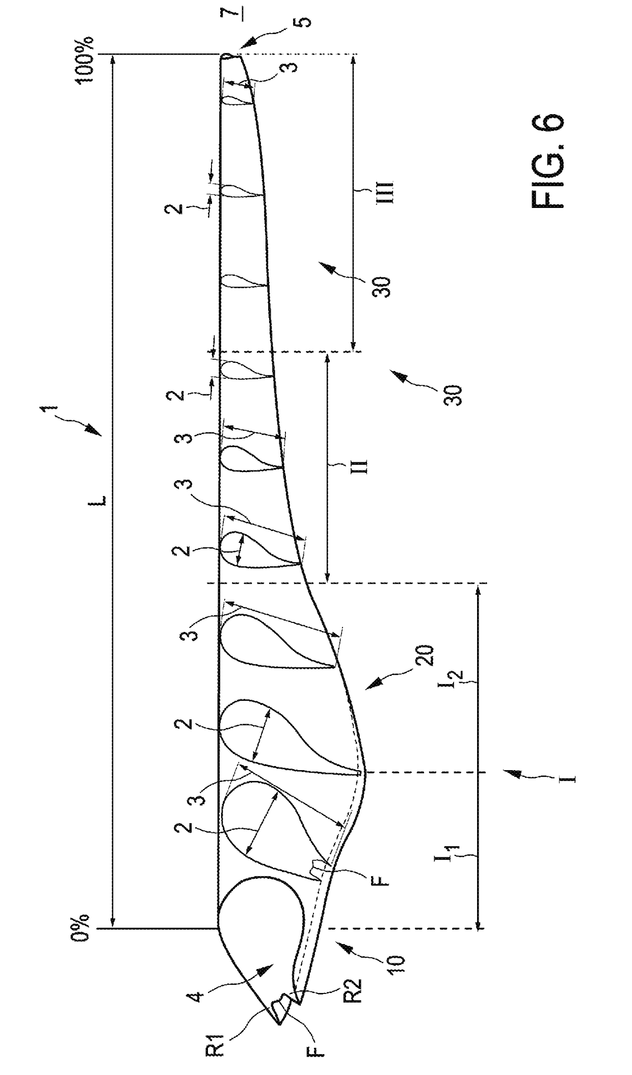
[0068]For the tip region III, FIG. 2 shows a rotor blade profile 30 substantially conforming to a standard profile, wherein the suction side S is of substantially convex form, and the pressure side D is of substantially concave or straight form.

[0069]FIG. 3 shows a rotor blade profile 20 of a rotor blade 1 in the hub region with a truncated trailing edge F, wherein the trailing edge has a relative trailing edge th...


PUM


Abstract

A rotor blade having a suction side and a pressure side for a wind power installation, comprising: a rotor blade root of a hub region for the attachment of the rotor blade to a rotor hub, and a rotor blade tip arranged toward that side of a tip region which is averted from the rotor blade root. In the region of the hub region, the rotor blade has, at least in part, a thickness profile which has a thorn-like extension at its trailing edge, wherein, in the region of the hub region, the thickness profile has, at least in part, a first thorn-like extension at the trailing edge at the suction side, and a second thorn-like extension at the trailing edge at the pressure side, and, in the region of the hub region, the thickness profile has, at least in part, a flow stabilizer and/or a vortex generator on the suction and/or pressure side.

Description

BACKGROUNDTechnical Field[0001]The invention relates to a rotor blade of a wind power installation, and to a wind power installation.Description of the Related Art[0002]Rotor blades for a rotor of a wind power installation are generally known. Such rotor blades have a profile (cross-sectional profile) which makes allowance for the special aerodynamic requirements.[0003]A wind power installation has, for example, an aerodynamic rotor with multiple rotor blades, and is shown by way of example in FIG. 1. The aerodynamic characteristics of such rotor blades influence the performance of the rotor blades and thus of the wind power installation. To increase the performance of a rotor blade, the profiles thereof are optimized. In order, for example, to ensure electricity production which is as constant as possible in regions with light winds, specifically in particular at inland sites, the aerodynamic rotors have a rotor diameter which may amount to more than 80 meters. In the case of such ...

Claims


Application Information

Patent Timeline
IPC IPC(8): F03D1/06
CPCF03D1/0641F05B2240/301F05B2240/302F05B2260/96F16C2360/31Y02E10/72
Inventor HOFFMANN, ALEXANDER
Owner WOBBEN PROPERTIES GMBH
Why Eureka
Try Eureka