High capture efficiency wave energy converter withimproved heave, surge and pitch stability

a wave energy converter and high-efficiency technology, applied in buoyancy control, mechanical equipment, machines/engines, etc., can solve the problems of high capital cost (capex/mw), lack of convergence, and inability to capture significant surge wave energy, etc., and achieve the effect of small volum

Active Publication Date: 2019-02-07
ROHRER TECH
View PDF0 Cites 9 Cited by
  • Summary
  • Abstract
  • Description
  • Claims
  • Application Information

AI Technical Summary

Benefits of technology

[0028]It is desirable to have the first floating body as wide as possible and oriented parallel to oncoming wave fronts to intercept the maximum amount of energy contained in a wave front per unit float volume, mass, and hence cost. While it is possible to have one or more second body(bodies) hinged to the first body in the form

Problems solved by technology

While a surface buoy with a seabed-attached tensioned-cable drive requires only one floating body, it can only capture heave and not significant surge wave energy.
Wave energy's delayed commercialization is due in large part to the profusion of unique ocean Wave Energy Converter (WEC) design concepts being proposed resulting in the lack of “convergence” on a generally recognized “best WEC” (most cost effective and reliable WEC design).
The high capital cost (CapEx/MW) and low wave energy capture efficiency of the few first-generation WEC designs, which have proceeded to ocean trials at large scale to date, have also dampened investment interest.
A reaction body can be motion stabilized if it is large enough to span at least two wave crests but with typical ocean wave lengths of 100-300 meters, this can become cost prohibitive.
Because the cost (CapEx) of marine bodies and vessels are approximately proportional to their volume and displacement or weight, increasing the size, weight, and hence cost of at least one WEC body to stabilize that body and increase the

Method used


Image

  • High capture efficiency wave energy converter withimproved heave, surge and pitch stability
  • High capture efficiency wave energy converter withimproved heave, surge and pitch stability
  • High capture efficiency wave energy converter withimproved heave, surge and pitch stability

Examples


Embodiment Construction

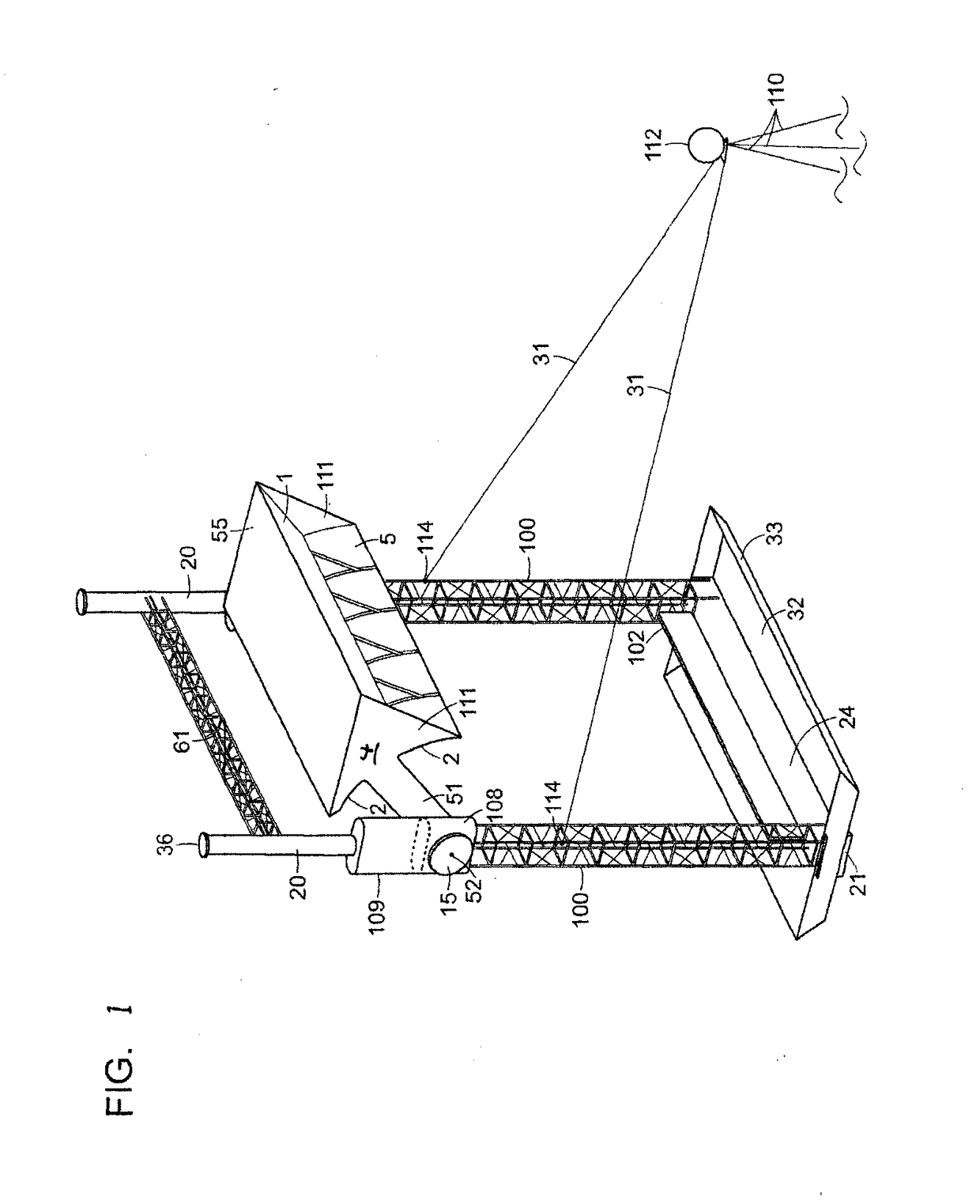
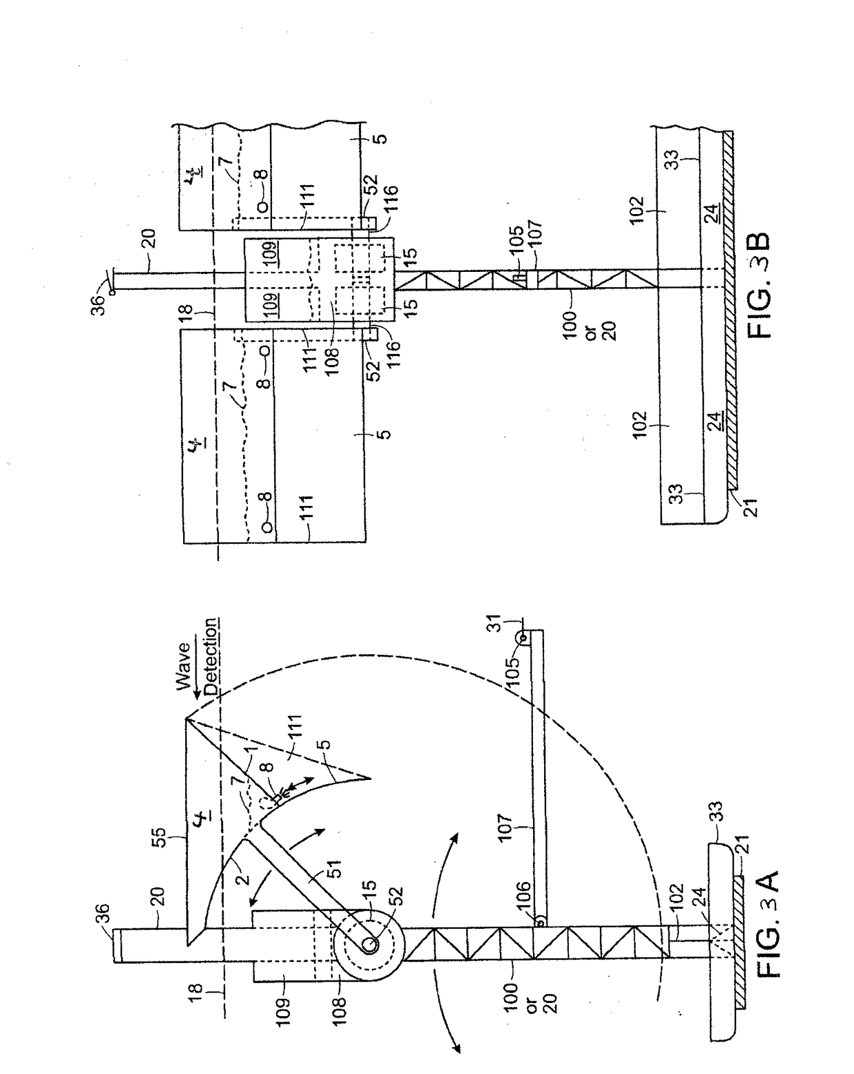
[0052]Referring to FIG. 1, a two-body WEC comprising a first body elongated wave front parallel surface float 4 (having deck 55, front face 1, rear wall 2 with lower extension 5, and side shields 111) is shown attached via swing or drive arms 51, pivoting about point 52, to a second semi-submersed twin vertical spar frame or body (having 20 upper frame column with top access hatch 36, mid-frame 109w PTO 5 housing, 100 lower frame, and 61 frame cross beam) pivotably attached 114 to a submersed buoyant mooring buoy 112 by twin mooring cables 31 which mooring buoy is affixed to the seabed by three tensioned mooring cables 110. This embodiment achieves several of the objectives of the subject disclosure including; 1. A second body (twin vertical spar semi-submersible frame) partially stabilized against unwanted heave and pitch motion by both horizontal 32 and vertical 33 and 102 drag plates, seawater ballast in ballast tank 108, and solid ballast 21, 2. Self-orientation of the Float 4 p...


PUM


Abstract

A means for improving the motion stability of a floating, semi-submerged, or submerged body used in, multi-capture-mode wave energy converters (WECs) having two or more bodies, against wave-induced heave, surge, and pitching forces, while reducing the size, mass and cost of such bodies or bases, thus improving the relative motion and hence capture efficiency of such WECs over a broad spectrum of wave periods and wave heights. Stabilizing counter moments against wave-induced motion are substituted by strategic placement of drag plates or planes entraining seawater mass or water-filled cavities within, or attached to, the bases and/or at least one tensioned seabed-affixed cable. The base or reaction-body stabilizing means is disclosed in a two-body multi-capture-mode, deep-water, surface-deployed, wave-terminator-type WEC to concurrently increase wave energy capture efficiency and reduce the volume, mass, and capital cost of the WEC's stabilized reaction body or base.

Description

CROSS-REFERENCE TO RELATED APPLICATIONS[0001]This application claims the benefit of U.S. Provisional Application Ser. No. 62 / 707,920, filed Nov. 24, 2017 and U.S. Provisional Application Ser. No. 62 / 762,534, filed May 8, 2018, the contents both of which are incorporated in their entirety herein by reference. This is a Continuation-In-Part of U.S. Regular Utility application Ser. No. 15 / 285,539, filed on Oct. 5, 2016, now U.S. Pat. No. 10,094,356, issued Oct. 9, 2018, which claimed the benefit of U.S. Provisional Application Ser. No. 62 / 284,640 filed Oct. 5, 2015, and which is a Continuation-In Part of U.S. Regular Utility application Ser. No. 14 / 530,723, filed Nov. 1, 2014, now U.S. Pat. No. 9,863,395, issued Jan. 9, 2018, which is a Continuation-In-Part of U.S. Regular Utility application Ser. No. 14 / 101,325, filed Dec. 9, 2013, now U.S. Pat. No. 9,127,640, issued Sep. 8, 2015, which is a Continuation-In-Part of U.S. Regular Utility application Ser. No. 13 / 506,680, filed May 8, 201...

Claims


Application Information

Patent Timeline
IPC IPC(8): F03B13/18F03B13/10
CPCF03B13/182F03B13/1855F03B13/10F05B2270/18F03B13/20Y02E10/20Y02E10/30
Inventor ROHRER, JOHN W.
Owner ROHRER TECH
Why Eureka
Try Eureka