Temperature detection module

a technology of temperature detection module and temperature, applied in secondary cells, cell components, instruments, etc., can solve the problems of thermal insulation electrical wire losing an excess length and tensile force, and requiring countermeasures, and achieve the effect of tensile for

Active Publication Date: 2019-02-07
AUTONETWORKS TECH LTD +2
View PDF0 Cites 2 Cited by
  • Summary
  • Abstract
  • Description
  • Claims
  • Application Information

AI Technical Summary

Benefits of technology

[0017]When a tensile force is applied to the thermistor electrical wire, the tensile force is reduced while the folded portion deforms. An excess load is prevented from being applied to the position at which the thermistor electrical wire is held.
[0018]According to

Problems solved by technology

However, with a conventional means, the excess length portions provided at the drawing ends of the thermistor electrical wires are in a free state, that is, they are not managed, and thus, in a case where the thermistor electrical wires are pulled accidentally or the like, for example, there is a risk

Method used


Image

  • Temperature detection module
  • Temperature detection module
  • Temperature detection module

Examples


embodiments

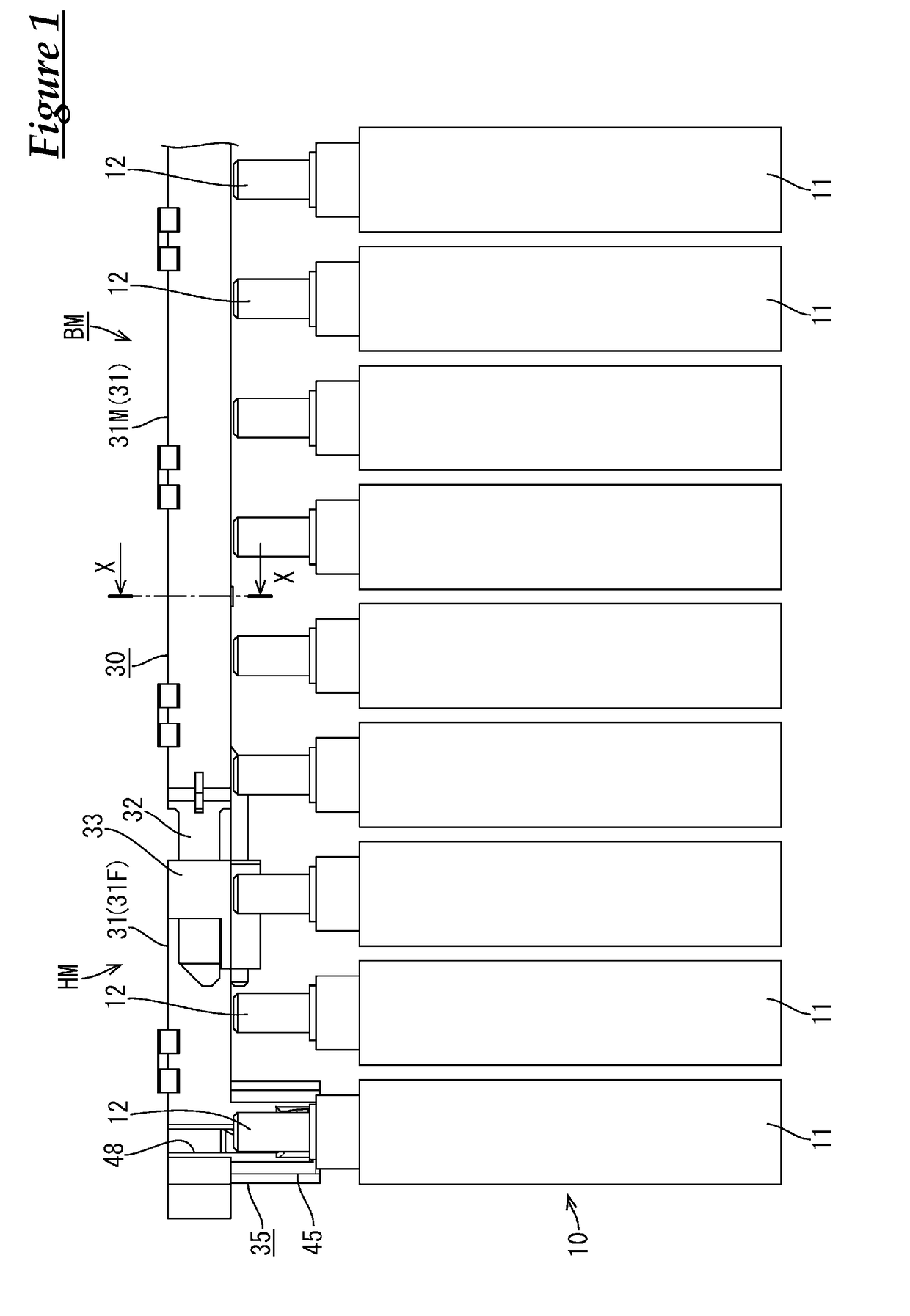
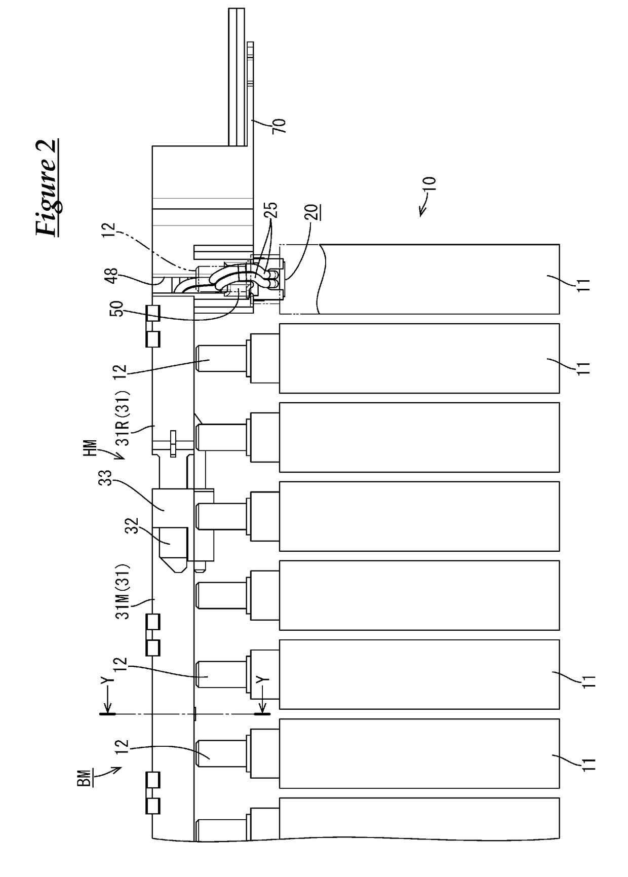
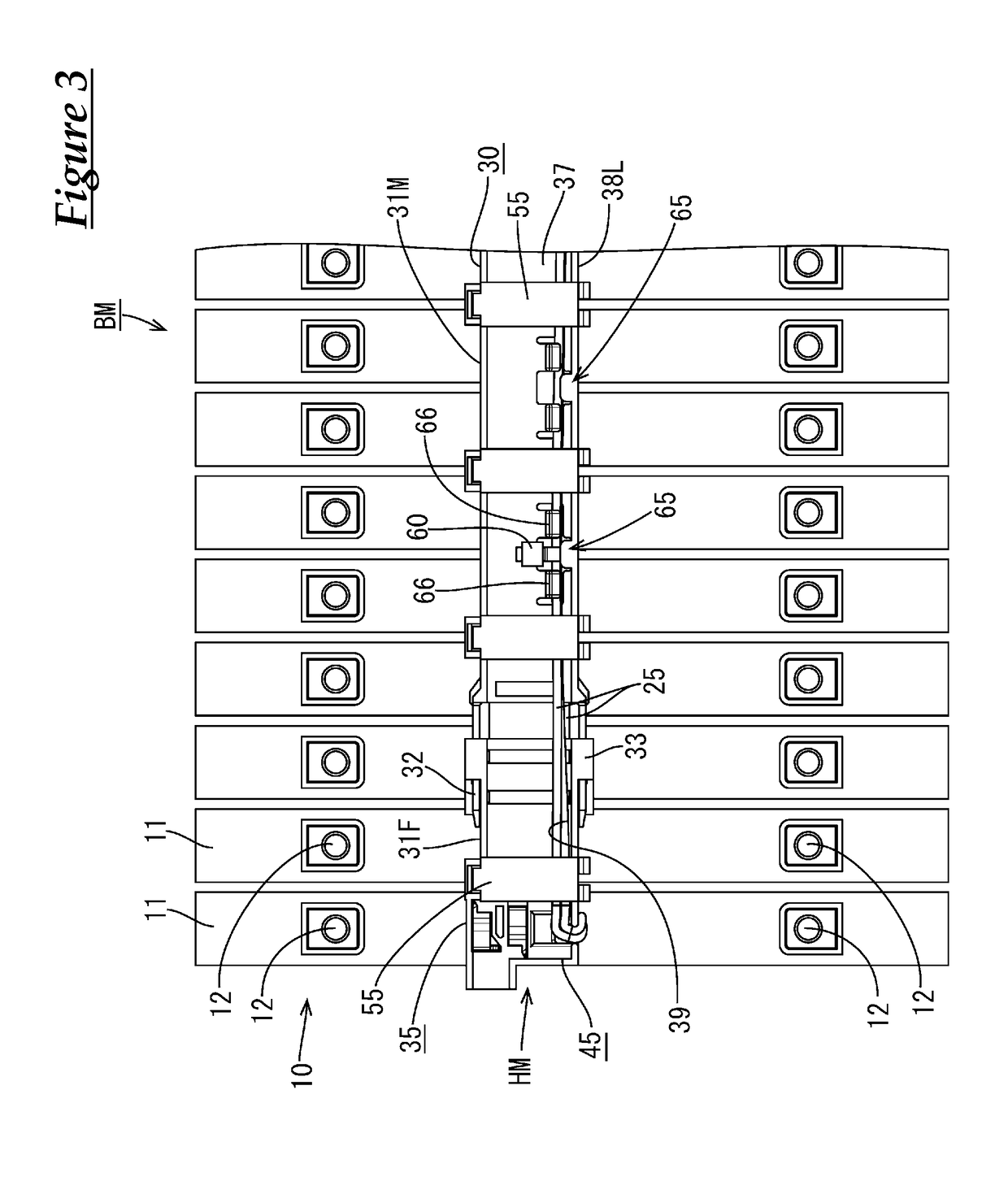
[0041]An embodiment will be described based on FIGS. 1 to 22. As shown in FIGS. 1 to 4, a battery module BM includes an electric cell group 10 in which a plurality of electric cells 11 (one example of power storage elements) each having a positive electrode terminal 12 and a negative electrode terminal 12 are arranged side-by-side, and the electrode terminals 12 (positive electrode and negative electrode) of adjacent electric cells 11 are successively connected using bus bars (not shown), and thereby this battery module BM is formed.

[0042]A temperature detection module HM according to the present embodiment is mounted on an upper surface of the above-described electric cell group 10.

[0043]As shown in FIG. 3, the temperature detection module HM is configured including a thermistor mounting member 30 (simply referred to as “mounting member 30” hereinafter) made of a synthetic resin and a plurality of thermistors 20 (see FIG. 9) that are mounted on this mounting member 30, and is arran...


PUM


Abstract

A temperature detection module includes a thermistor configured to detect the temperature of an electric cell, a thermistor electrical wire drawn from the thermistor, a thermistor holding portion configured to hold the thermistor movably in a direction in which the thermistor comes into contact with and separates from the electric cell in a form in which the thermistor is biased to move toward the electric cell, and an electrical wire routing path in which the thermistor electrical wire is routed in one direction. The electrical wire routing path is provided with a holding means for holding a midpoint of the thermistor electrical wire that is drawn from the thermistor and routed along the electrical wire routing path in a form in which a drawing end of the thermistor electrical wire is provided with an excess length portion having a predetermined length in order to allow movement of the thermistor.

Description

CROSS REFERENCE TO RELATED APPLICATIONS[0001]This application claims the priority of Japanese patent application JP2016-016873 filed on Feb. 1, 2016, the entire contents of which are incorporated herein.TECHNICAL FIELD[0002]The technology disclosed in this specification relates to a temperature detection module that is provided in an electricity storage module.BACKGROUND ART[0003]Battery modules obtained by connecting a plurality of electric cells side by side are used as power source apparatuses of electric automobiles and hybrid cars. In such battery modules, if the temperature of electric cells rises to a high temperature, the lifetime and the like of the electric cells are adversely affected, and thus a means has been devised in which the temperatures of the electric cells are monitored using a temperature detection module equipped with a thermistor, and a means disclosed in Patent Document 1 (JP2013-157123A) below is known, for example.[0004]The temperature detection module inc...

Claims


Application Information

Patent Timeline
IPC IPC(8): G01K7/22H01M10/48H01M2/10G01K1/08H01M2/20H01M50/209H01M50/298H01M50/514H01M50/569
CPCG01K7/223H01M10/486H01M2/1077G01K1/08H01M2/202G01K7/22G01K1/146H01M10/425H01M10/482Y02E60/10H01M50/514H01M50/209H01M50/569H01M50/298
Inventor SHIMODA, HIROKITAKASE, SHINICHIMATSUMURA, NOBUYUKIITO, YOSHINORITAKAHASHI, HIDEO
Owner AUTONETWORKS TECH LTD
Why Eureka
Try Eureka