Fourier lens, method for designing fourier lens, and schlieren apparatus

Active Publication Date: 2019-02-07
NANKAI UNIV
View PDF1 Cites 0 Cited by
  • Summary
  • Abstract
  • Description
  • Claims
  • Application Information

AI Technical Summary

Benefits of technology

The present invention relates to a Fourier lens that includes a substrate and a plurality of cuboid waveguides arranged on the substrate in parallel and spaced from each other at a preset interval. The materials of the substrate and waveguides are all transparent to the working waveband and the width of the waveguides is designed to correspond to different phase delays, thus creating an array antenna with sub-wavelength structure that regulates the incident light and allows for a wider range of working angles. The technical effects of the invention include increased range of working angles, improved light control, and reduced waveguides distortion.

Problems solved by technology

Spatial spectrum distortion means that there is a difference between the ideal and practical positions of the light spot, on a back focal plane of a Fourier lens, of parallel light rays incident onto the Fourier lens.
As can be known from the aberration theory, in the process of eliminating the spherical aberration and coma aberration of the lens, a certain amount of distortion will inevitably be left.

Method used


Image

  • Fourier lens, method for designing fourier lens, and schlieren apparatus
  • Fourier lens, method for designing fourier lens, and schlieren apparatus
  • Fourier lens, method for designing fourier lens, and schlieren apparatus

Examples


first embodiment

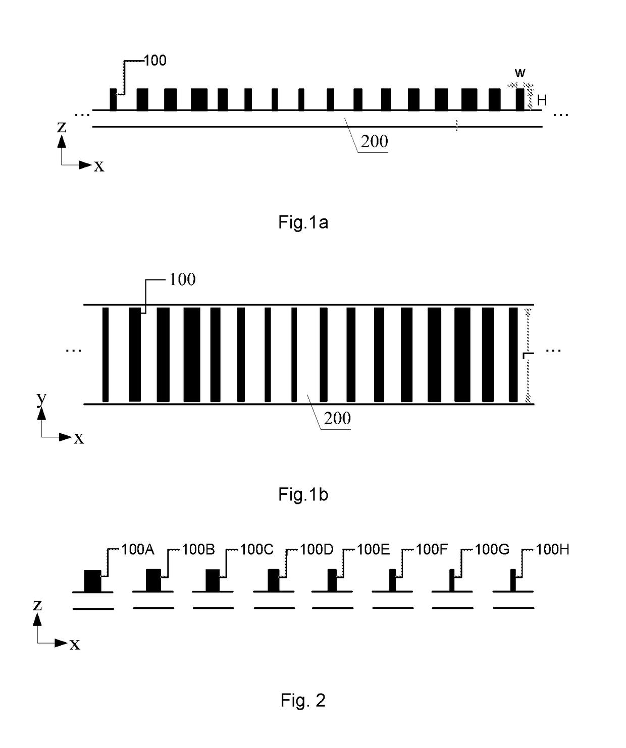
[0050]FIG. 1a is a side view (in the x-z plane) showing a schematic structure of a Fourier lens provided by an embodiment of the present invention, and FIG. 1b is a top view (in the x-y plane) showing the schematic structure of the Fourier lens provided by the embodiment of the present invention. In the figures, the x direction is a direction perpendicular to the waveguides, the y direction is a direction parallel to the waveguides, the z direction is a direction along which light is propagated, W represents the width of the waveguide, H represents the height of the waveguide, and L represents the length of the waveguide.

[0051]As shown in FIGS. 1a and 1b, the embodiment of the present invention provides a Fourier lens, which includes a substrate 200 and a plurality of cuboid waveguides 100. The plurality of waveguides 100 are arranged on the substrate 200 in parallel and spaced from each other at a preset interval. The waveguides 100 have a plurality of widths, the waveguides 100 of...

second embodiment

[0067]FIG. 8 is a schematic flow chart of a method for designing a Fourier lens according to an embodiment of the present invention. As shown in FIG. 8, the method includes steps as follows.

[0068]Step S801, the material of the substrate and the material of the waveguides are determined, according to the working waveband of the Fourier lens to be designed.

[0069]The material of the substrate and the material of the waveguides are selected according to the working waveband of the Fourier lens to be designed. It is required that the refractive index of the material of the waveguides should be greater than 2.5, and the material of the substrate and the material of the waveguides are both transparent to the working waveband. For example, if the working waveband of the Fourier lens to be designed is 1100 nm-1700 nm, amorphous silicon waveguides (the refractive index of amorphous silicon is 3.5, with no absorption) may be selected, and the substrate may be a glass substrate, a silicon nitri...

third embodiment

[0096]FIG. 11 is a schematic structure diagram of a schlieren apparatus provided by an embodiment of the present invention. As shown in FIG. 11, along a propagation direction of the incident light, the schlieren apparatus sequentially includes a light source, a collimating lens L1, a cavity, a schlieren head, a first lens L2, a diaphragm, a second lens L3 and an outlet. Each of the first lens L2 and the second lens L3 is the Fourier lens as described in the first embodiment, and the cavity is configured for accommodating a test fluid flowing through the schlieren apparatus.

[0097]The schlieren apparatus is a device that is very useful in aerodynamics and combustion dynamics, and can be applied to flame photography and flow visualization technologies. The diaphragm used in the schlieren apparatus may be a knife edge, a high pass filter, a bandpass filter or the like. For an object of weak phase, a phase change may be converted into an intensity change by using a high pass filter or bl...


PUM


Abstract

Provided are a Fourier lens, a method for designing a Fourier lens, and a schlieren apparatus. The Fourier lens includes a substrate and a plurality of cuboid waveguides. The plurality of waveguides are arranged on the substrate in parallel and spaced from each other at a preset interval. The material of the substrate and the material of the waveguides are all transparent to the working waveband of the Fourier lens. The preset interval is smaller than a quotient obtained by dividing a center wavelength of the working waveband by the refractive index of the substrate. The waveguide has a plurality of widths, and the waveguides of different widths correspond to different phase delays. The individual waveguides are arranged on the substrate according to phase delays required at different positions. According to the embodiments, the range of the working angle of the Fourier lens can be increased.

Description

TECHNICAL FIELD[0001]The present invention relates to the technical field of optics, and particularly to a Fourier lens, a method for designing a Fourier lens, and a schlieren apparatus.BACKGROUND ART[0002]Different from a conventional imaging lens, a Fourier lens may exhibit, on a spectrum plane thereof, an intensity distribution assuming a linear relationship with the spatial frequency of incident light, and it has important applications in many fields, such as spatial light filtering, holography, information processing, compressed sensing and high-resolution imaging.[0003]Spatial spectrum distortion means that there is a difference between the ideal and practical positions of the light spot, on a back focal plane of a Fourier lens, of parallel light rays incident onto the Fourier lens. In order to guarantee accurate spatial spectrum distribution, it is necessary to make the Fourier lens produce a distortion value having an equal magnitude but an opposite sign to the nonlinear err...

Claims


Application Information

Patent Timeline
IPC IPC(8): G02B3/08G02B27/00G02B6/122G02B27/54G02B6/10
CPCG02B27/0087G02B6/122G02B27/0012G02B27/54G02B6/107G02B3/08G02B5/1876G02B27/46
Inventor CHEN, SHUQILIU, WENWEICHENG, HUATIAN, JIANGUO
Owner NANKAI UNIV
Why Eureka
Try Eureka