
Flat plate type fuel cell

Inactive Publication Date: 2019-02-14
MORIMURA SOFC TECH CO LTD
View PDF2 Cites 4 Cited by
  • Summary
  • Abstract
  • Description
  • Claims
  • Application Information

AI Technical Summary

Benefits of technology

The patent describes a method that improves the temperature distribution in a fuel cell, which results in increased power generation efficiency. This is achieved by combining the gas flow channels for fuel gas and oxidizer gas to achieve a uniform temperature across the cell. Additionally, the patent describes a planar fuel cell apparatus that can provide high output voltage by stacking multiple planar fuel cell units.

Problems solved by technology

However, the technique described in Patent Document 1 has a problem that the technique cannot improve (uniformize) the cell in-plane temperature distribution to a sufficient degree and cannot improve the power generation efficiency of the single fuel cell itself.
However, studies conducted by the present inventors have revealed that, in the case where a higher efficiency is sought by a method of changing the flows of the gasses, as shown in FIG. 13A, uniformizing of the temperature distribution does not necessarily result in an increase in the output voltage.

Method used


Image

  • Flat plate type fuel cell
  • Flat plate type fuel cell
  • Flat plate type fuel cell

Examples


first embodiment

[First Embodiment]

[0062]a) First, the schematic structure of a planar fuel cell apparatus of the first embodiment will be described.

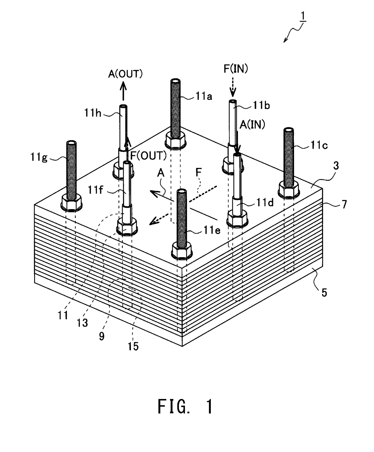
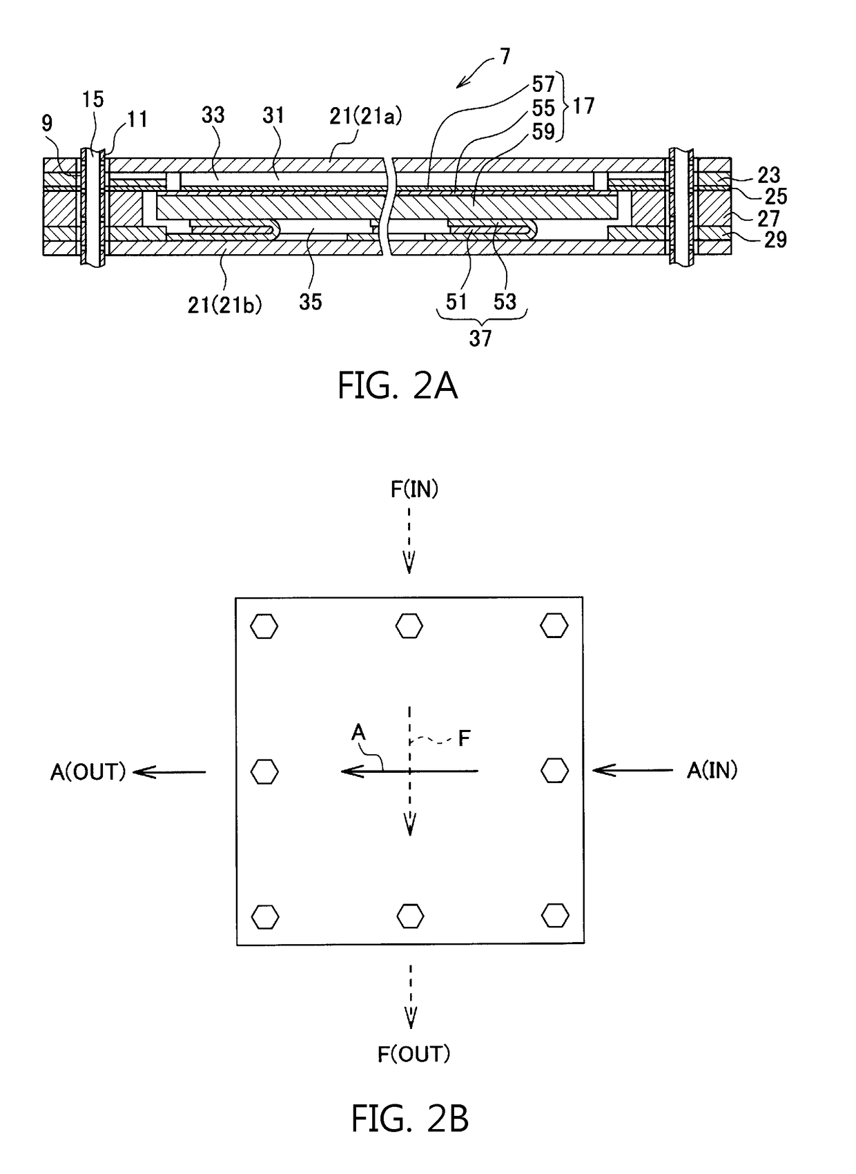
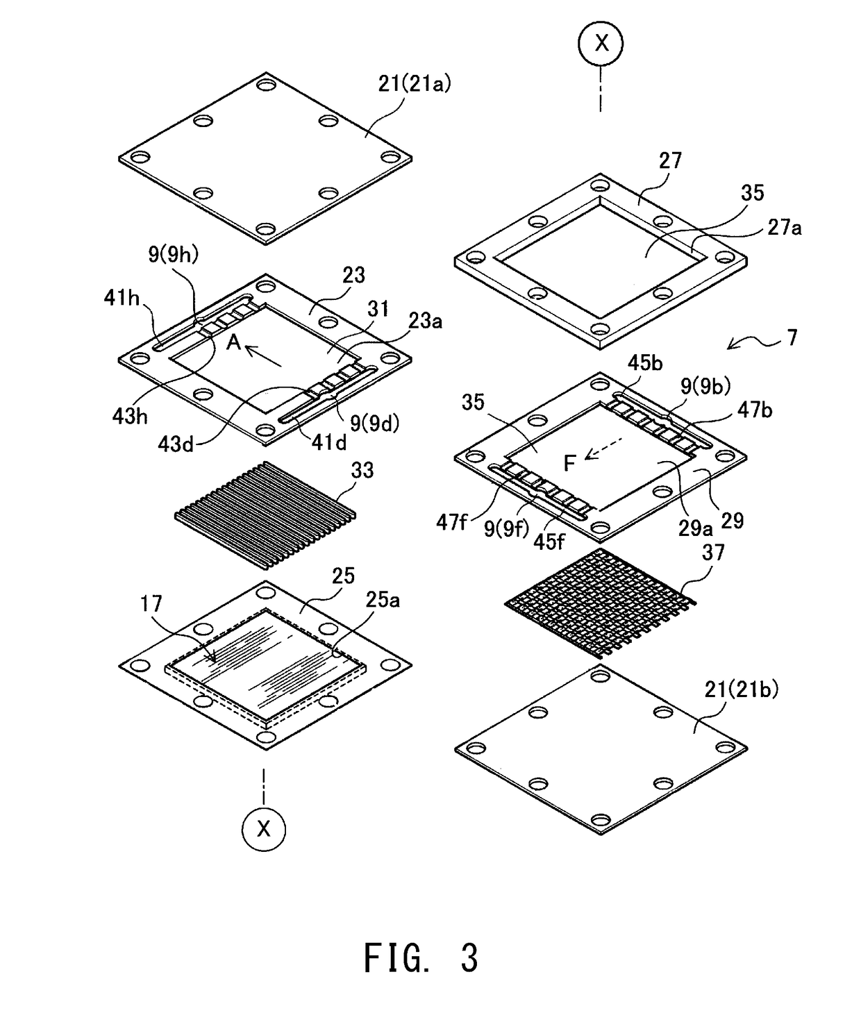
[0063]As shown in FIG. 1, a planar fuel cell apparatus (hereinafter, may be referred to merely as “fuel cell apparatus”) 1 of the first embodiment generates electricity by use of fuel gas (e.g., hydrogen) and oxidizer gas (e.g., air, more specifically oxygen contained in air) supplied thereto.

[0064]In the drawings, oxidizer gas is denoted by “A,” and fuel gas is denoted by “F.” Also, “IN” indicates that gas is introduced, and “OUT” indicates that gas is discharged. Further, for convenience of description, directions such as “upper” and “lower” are mentioned on the basis of directions in the drawings, but are not intended to specify the directivity of an actual fuel cell stack.

[0065]The fuel cell apparatus 1 of the first embodiment is a planar (rectangular parallelepiped) solid oxide fuel cell apparatus and is a fuel cell stack configured such that a plu...

second embodiment

[Second Embodiment]

[0134]Next, a second embodiment will be described; however, the description of contents similar to those of the first embodiment is omitted. In the following description, structural members similar to those of the first embodiment are denoted by the same reference numerals as those of the first embodiment.

[0135]The fuel cell apparatus 1 of the second embodiment is configured such that the oxidizer gas flow channel and the fuel gas flow channel are prescribed to meet the above-described “flow channel disposition condition 1” of the first embodiment.

[0136]Specifically, as shown in FIG. 6A, the centroid Cai of the oxidizer gas inlets Ain is disposed at the midpoint of the third side H3 of the first frame W1, and the centroid Cao of the oxidizer gas outlets Aout is disposed at a position offset from the midpoint of the fourth side H4 of the first frame W1 toward the centroid Cfi of the fuel gas inlets Fin. As a result, the oxidizer gas flows from the right side of FIG...

third embodiment

[Third Embodiment]

[0139]Next, a third embodiment will be described; however, the description of contents similar to those of the first embodiment is omitted. In the following description, structural members similar to those of the first embodiment are denoted by the same reference numerals as those of the first embodiment.

[0140]The fuel cell apparatus 1 of the third embodiment is configured such that the oxidizer gas flow channel and the fuel gas flow channel are prescribed to meet the following “flow channel disposition condition 2” as well as “flow channel disposition condition 1” of the first embodiment.

[0141]Specifically, in the fuel cell apparatus 1 of the third embodiment, as shown in FIG. 7, as viewed in the stacking direction, the centroid Cfo of the fuel gas outlets Fout is disposed at a position located a distance of 0.1 Xp or less from the reference line Lf toward the boundary line Lfp or a distance of 0.1 Xm or less from the reference line Lf toward the boundary line Lfm...


PUM


Abstract

A planar fuel cell apparatus (1), as viewed in a stacking direction, includes a first rectilinear line which connects a centroid Cfi of fuel gas inlets and a centroid Cfo of fuel gas outlets, and a second rectilinear line which connects a centroid Cai of oxidizer gas inlets and a centroid Cao of oxidizer gas outlets cross each other. The planar fuel cell apparatus employs cross-flow design in which a fuel gas flow channel and an oxidizer gas flow channel cross each other. In the planar fuel cell apparatus of the cross-flow design, as viewed in the stacking direction, the centroid Cao of the oxidizer gas outlets is located closer to the centroid Cfi of the fuel gas inlets than to the centroid Cfo of the fuel gas outlets.

Description

CROSS REFERENCE TO RELATED APPLICATIONS[0001]This application is a National Stage of International Application No. PCT / JP2016 / 001780 filed Mar. 28, 2016, claiming priority based on Japanese Patent Application No. 2015-073681 filed Mar. 31, 2015, the contents of all of which are incorporated herein by reference in their entirety.TECHNICAL FIELD[0002]The present invention relates to a flat plate type fuel cell (hereinafter referred to as a “planar fuel cell apparatus”) which includes a single fuel cell having an anode layer, a cathode layer, and a solid electrolyte layer sandwiched therebetween.BACKGROUND ART[0003]A conventionally known fuel cell apparatus is, for example, a solid oxide fuel cell (hereinafter, may be referred to as SOFC) apparatus which uses solid electrolyte (solid oxide).[0004]The SOFC apparatus uses, for example, a planar single fuel cell having an anode layer provided on one side of a solid electrolyte layer and in contact with fuel gas, and a cathode layer provid...

Claims


Application Information

Patent Timeline
IPC IPC(8): H01M8/12H01M8/2432H01M8/02
CPCH01M8/12H01M8/2432H01M8/02H01M2008/1293H01M8/0271H01M8/2483Y02E60/50
Inventor YOSHIZAKI, HIROTOSHISHICHIDA, TAKAFUMI
Owner MORIMURA SOFC TECH CO LTD
Learn More