Process for producing membrane/electrode assembly for polymer electrolyte fuel cell

Inactive Publication Date: 2010-12-16
ASAHI GLASS CO LTD
View PDF10 Cites 18 Cited by
  • Summary
  • Abstract
  • Description
  • Claims
  • Application Information

AI Technical Summary

Benefits of technology

[0042]By the present invention, it is possible to produce a membrane / electrode assembly for a polymer electrolyte fuel cell producing a high output voltage in a wide current density range.BRIEF EXPLANATION OF THE DRAWINGS
[0043]FIG. 1 is a schematic cross sectional view showing an example of a membrane / electrode assembly in a polymer electrolyte fuel cell.
[0044]FIG. 2 is a view for explaining an example of the process for producing a membrane / electrode assembly for a polymer electrolyte fuel cell of the present invention.
[0045]FIG. 3 is a view for explaining an example of the process for producing a membrane / electrode assembly for a polymer electrolyte fuel cell of the present invention.
[0046]FIG. 4 is a view for explaining an example of the process for producing a membrane / electrode assembly for a polymer electrolyte fuel cell of the present invention.
[0047]FIG. 5 is a view for explaining an example of the process for producing a membrane / electrode assembly for a polymer electrolyte fuel cell of the present invention.EXPLANATION OF NUMERALS

Problems solved by technology

), but it also has a demerit that its exhaust heat is hard to be used efficiently for e.g. auxiliary power.

Method used


Image

  • Process for producing membrane/electrode assembly for polymer electrolyte fuel cell
  • Process for producing membrane/electrode assembly for polymer electrolyte fuel cell
  • Process for producing membrane/electrode assembly for polymer electrolyte fuel cell

Examples


first embodiment

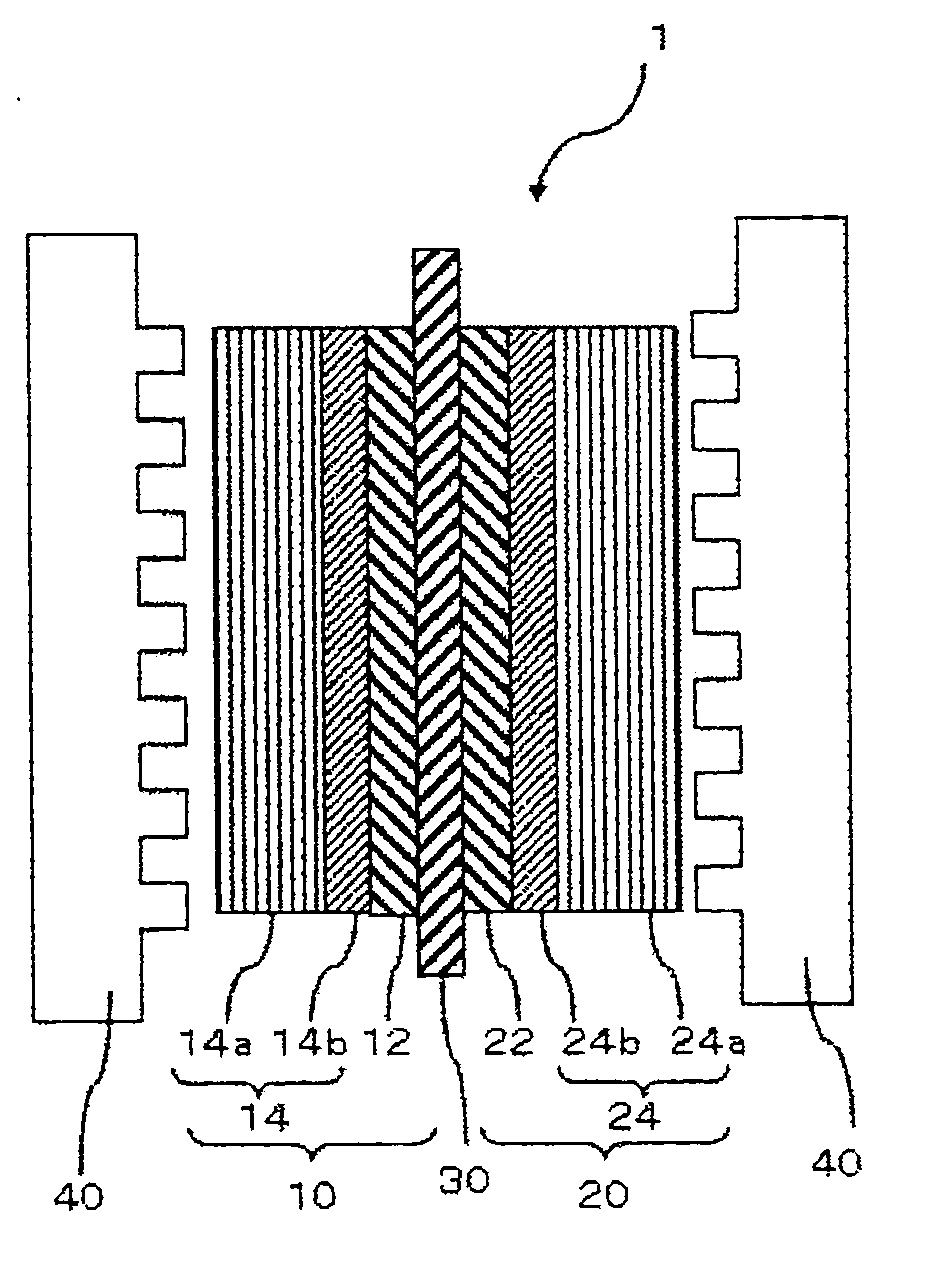
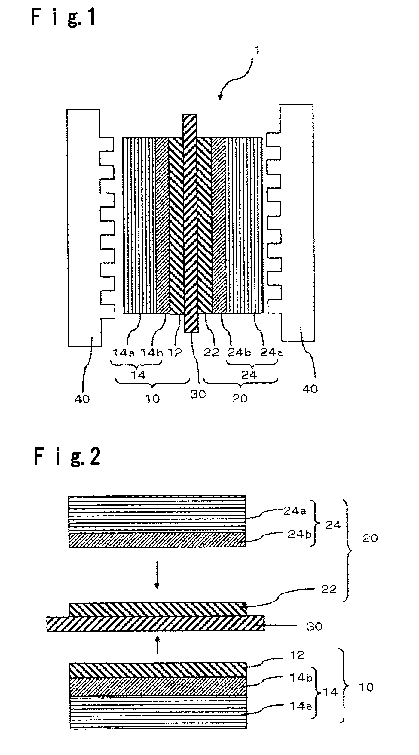
[0053]As a process for producing the membrane / electrode assembly 1 in this embodiment, a process having steps (1-1) to (1-4) is mentioned. This process is described with reference to FIG. 2.

[0054]Step (1-1): Gas diffusion layer 24-forming step

[0055]Step (1-2): Electrolyte membrane 30 with catalyst layer 22-forming step

[0056]Step (1-3): Anode 10-forming step

[0057]Step (1-4): Bonding step

[0058]Step (1-1): Gas diffusion layer 24-forming step

[0059]As the step (1-1), a step having the following steps (1-1-1) to (1-1-3) may be mentioned.

[0060]Step (1-1-1): Gas diffusion layer (1)24a-forming step

[0061]This step is a step of applying a gas diffusion layer (1)-coating fluid containing carbon fibers having a fiber diameter of from 1 μm to 50 μm and a proton conductive polymer, on a substrate, and drying it to form a gas diffusion layer (1)24a.

[0062]The carbon fibers preferably have a fiber diameter of from 2 μm to 40 μm, more preferably from 3 μm to 20 μm in order to obtain a sufficient gas ...

second embodiment

[0155]As another method for producing the membrane / electrode assembly 1, a method including steps (2-1) to (2-4) may be mentioned, and steps (2-1) to (2-4) may, specifically, be methods having the following steps.

[0156]Step (2-1): Gas diffusion layer 14-forming step[0157]Step (2-1-1): Gas diffusion layer (1)14a-forming step[0158]Step (2-1-2): Removal step[0159]Step (2-1-3): Gas diffusion layer (2)14b-forming step

[0160]or[0161]Step (2-1-4): Gas diffusion layer (2)14b-forming step[0162]Step (2-1-5): Removal step[0163]Step (2-1-6): Gas diffusion layer (1)14a-forming step

[0164]Step (2-2): Electrolyte membrane 30 with catalyst layer 12-forming step[0165]Step (2-2-1): Electrolyte membrane 30-forming step[0166]Step (2-2-2): Catalyst layer 12-forming step

[0167]Step (2-3): Cathode 20-forming step[0168]Step (2-3-1): Gas diffusion layer (1)24a-forming step[0169]Step (2-3-2): Removal step[0170]Step (2-3-3): Gas diffusion layer (2)24b-forming step[0171]Step (2-3-4): Catalyst layer 22-forming ste...

third embodiment

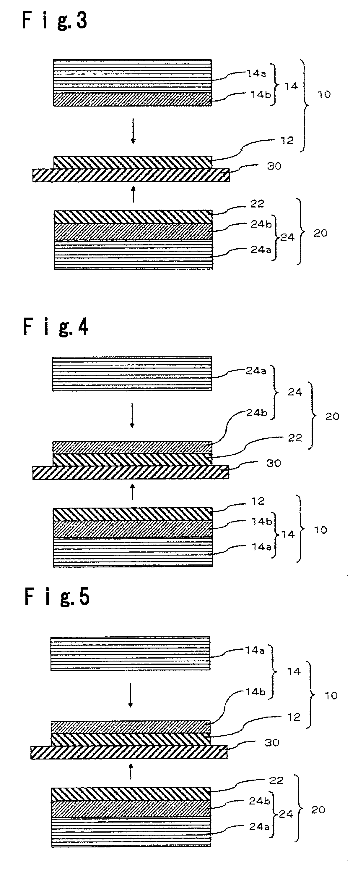
[0174]As another process for producing a membrane / electrode assembly 1, a process having steps (3-1) to (3-4) may be mentioned. This process will be described with reference to FIG. 4.

[0175]Step (3-1): Gas diffusion layer (1)24a-forming step

[0176]Step (3-2): Electrolyte membrane 30 with gas diffusion layer (2)24b and catalyst layer 22-forming step

[0177]Step (3-3): Anode 10-forming step

[0178]Step (3-4): Bonding step

[0179]Step (3-1): Gas diffusion layer (1)24a-forming step

[0180]Step (3-1) may, for example, be a method having steps (3-1-1) to (3-1-2).

[0181]Step (3-1-1): Gas diffusion layer (1)24a-forming step

[0182]This step is a step of applying a gas diffusion layer (1)-coating fluid containing carbon fibers having a fiber diameter of from 1 μm to 50 μm and a proton conductive polymer, on a substrate, to form a gas diffusion layer (1)24a. This step can be carried out in the same manner as step (1-1-1) of the first embodiment.

[0183]Step (3-1-2): Removal step

[0184]This step is a step of...


PUM

PropertyMeasurementUnit
Lengthaaaaaaaaaa
Lengthaaaaaaaaaa
Percent by massaaaaaaaaaa

Abstract

Provision of a process for producing a membrane / electrode assembly for a polymer electrolyte fuel cell which can produce a high output voltage in a wide current density range.A process for producing a membrane / electrode assembly for a polymer electrolyte fuel cell, comprising an anode and a cathode each having a catalyst layer, and an electrolyte membrane interposed between the catalyst layer of the anode and the catalyst layer of the cathode;said process comprising:a gas diffusion layer-forming step of applying a gas diffusion layer-coating fluid containing carbon fibers having a fiber diameter of from 1 μm to 50 μm and a proton conductive polymer, on a substrate to form a gas diffusion layer;a removal step of removing the substrate from the gas diffusion layer formed in the gas diffusion layer-forming step; anda step of disposing at least one such a gas diffusion layer thus prepared, on a surface of the catalyst layer of at least one of the anode and the cathode, on which the electrolyte membrane is not disposed.

Description

TECHNICAL FIELD[0001]The present invention relates to a process for producing a membrane / electrode assembly for a polymer electrolyte fuel cell.BACKGROUND ART[0002]Fuel cells using only hydrogen and oxygen and producing only water as a reaction product in principle, are focus of attention as power generation systems providing little adverse affect on the environment. Among them, in recent years, polymer electrolyte fuel cells each employing a proton conductive ion exchange membrane (polymer electrolyte membrane) as an electrolyte, are considered as prospective for automotive applications since they have low operation temperature, high power density and possibility of downsizing.[0003]A polymer electrolyte fuel cell comprises a membrane / electrode assembly comprising a polymer electrolyte membrane and electrodes (anode (fuel electrode) and a cathode (air electrode)) disposed on respective sides of the polymer electrolyte membrane; and separators each having a surface in which gas flow...

Claims


Application Information

Patent Timeline
IPC IPC(8): B32B38/10
CPCH01M8/0234H01M8/0243H01M8/1025H01M8/1039H01M2008/1095Y02P70/56H01M8/1007Y02P70/50Y02E60/50
Inventor TANUMA, TOSHIHIRO
Owner ASAHI GLASS CO LTD
Why Eureka
Try Eureka