
Backlight control circuit

Active Publication Date: 2008-05-15
RICHTEK TECH
View PDF6 Cites 4 Cited by
  • Summary
  • Abstract
  • Description
  • Claims
  • Application Information

AI Technical Summary

Benefits of technology

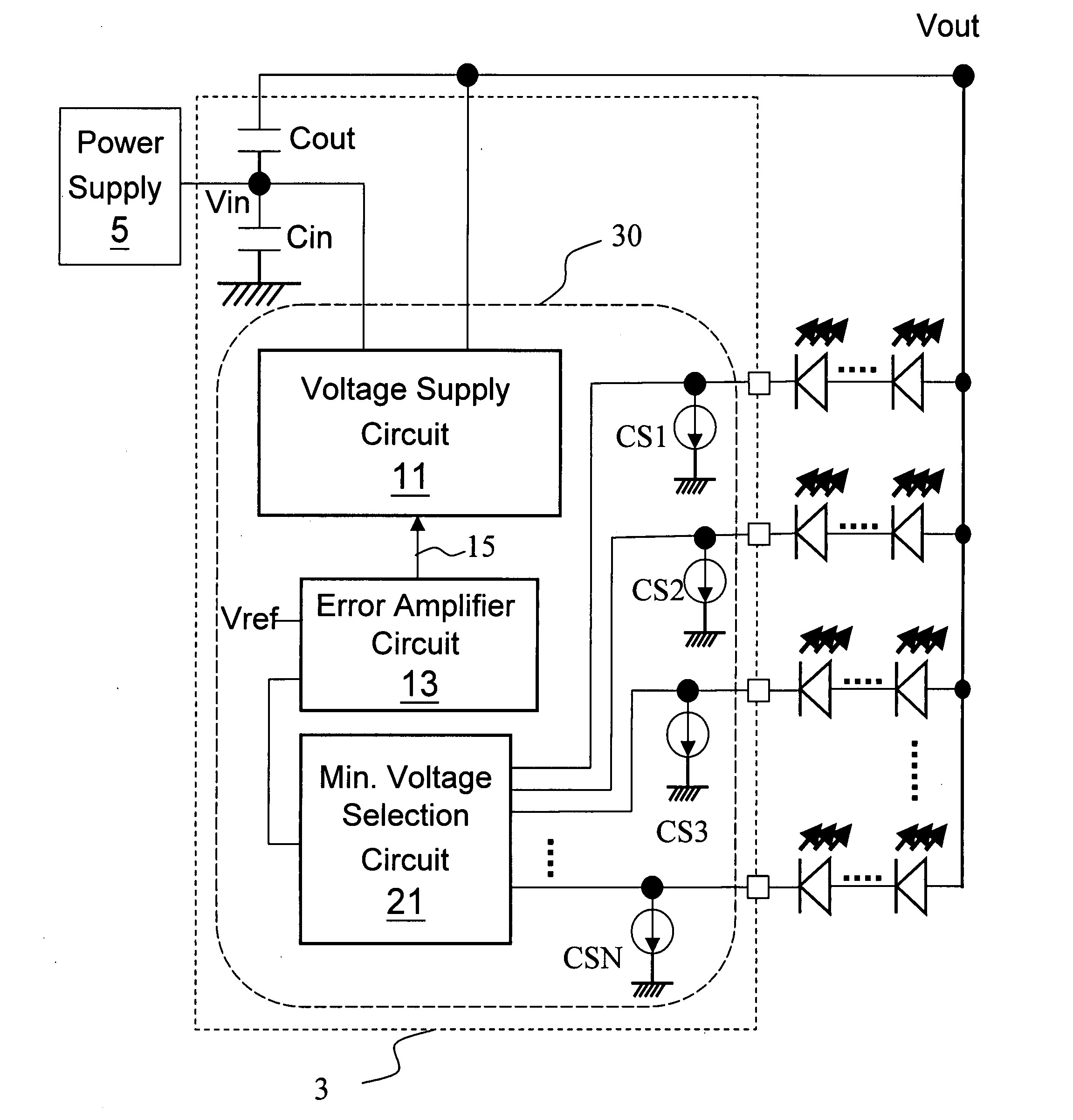
[0013]Preferably, the voltage supply circuit further comprises a noise filtering circuit to avoid a noise problem from the electrical connection between the output capacitor and the input terminal.

Problems solved by technology

However, it only checks the current on the path of LEDs L1-LN but does not check those on the other paths.
Correspondingly, a higher voltage rating capacitor is required for the output capacitor, which will increase the total cost of the backlight control circuit.

Method used


Image

  • Backlight control circuit
  • Backlight control circuit
  • Backlight control circuit

Examples


Embodiment Construction

[0027]The voltage of a white or blue LED may vary in a range from 3.3V to 4V due to manufacture deviation. To cope with it, in circuit design, the necessary output voltage Vout is calculated by 4V multiplied by the number of LEDs connected in series in a path. That is, if the number of LEDs in a path is more than or equal to 13, the Vout is higher than 50V. (4*13=52>50)

[0028]Considering the demand for thin thickness, small size, low parasitic resistance, environmental protection, and cost effectiveness, ceramic capacitor is currently the best choice for an LED backlight circuit. The nominal voltage ratings of ceramic capacitors are classified as: 6.3V / 10V / 16V / 25V / 50V / 100V / 200V / . . . , and the corresponding cost greatly increases as the rating goes higher (i.e., using a higher voltage rating capacitor). For example, the cost of a 100V rating capacitor is twice more than that of a 50V rating capacitor. In the prior art circuits shown in FIGS. 1, 4, and 5, if the number of LEDs in the...


PUM


Abstract

The present invention discloses a backlight control circuit, comprising: a voltage supply circuit, which is a boost converter circuit for receiving an input voltage from an input terminal and generating an output voltage to an output terminal, the output voltage being provided as an operating voltage for a plurality of light emitting devices; at least one input capacitor electrically connected between the input terminal and ground; and at least one output capacitor electrically connected between the output terminal and the input terminal.

Description

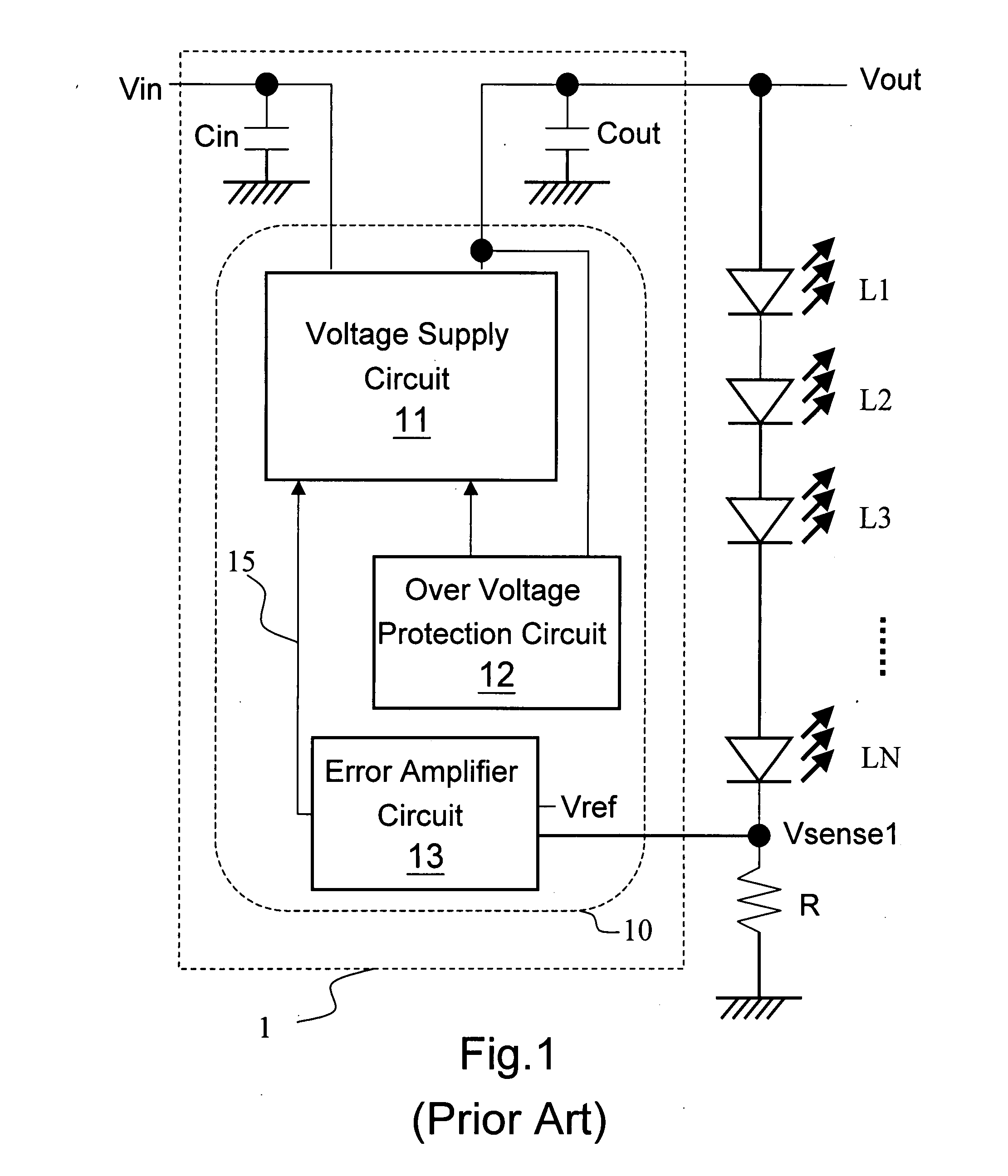
FIELD OF INVENTION[0001]The present invention relates to a backlight control circuit. More particularly, the present invention relates to a backlight control circuit which uses a low voltage rating capacitor to provide a high output voltage.BACKGROUND OF THE INVENTION[0002]In a liquid crystal display, a backlight control circuit is used which controls light emitting diodes (LEDs) to illuminate from the back side of a liquid crystal screen, so that a user can observe an image from the front side of the liquid crystal screen.[0003]In early days, LED backlight is used only in a small size screen, which does not require high backlight brightness. Therefore, the LEDs can be connected all in series or all in parallel. FIG. 1 shows a prior art circuit wherein all LEDs are connected in series. As shown in the figure, a backlight control circuit 1 comprises a backlight control integrated circuit 10 which includes an input terminal and an output terminal, wherein the input terminal is connect...

Claims


Application Information

Patent Timeline
IPC IPC(8): G05F1/00
CPCH05B33/0827H05B33/0815H05B45/46H05B45/38
Inventor LIU, JING-MENG
Owner RICHTEK TECH
Learn More