
Control system for regulating exciter power for a brushless synchronous generator

Inactive Publication Date: 2005-06-21
HONEYWELL INT INC
View PDF38 Cites 26 Cited by
  • Summary
  • Abstract
  • Description
  • Claims
  • Application Information

AI Technical Summary

Benefits of technology

[0014]The PMG voltage regulator further includes a direct current (DC) to direct current (DC) converter. In one implementation, a variable DC voltage is input into the DC to DC converter, a current signal from a constant DC voltage output line is output from the DC to DC converter and fed back through a current conditioning circuit and then input into the DC to DC converter for short circuit protection. The voltage signal from the constant DC voltage output line is also output from the DC to DC converter and fed back through a voltage feedback circuit and then input into the DC to DC converter. This feedback of the voltage signal in conjunction with the input from the voltage reference helps maintain a stable output from the DC / DC converter.
[0016]The present invention offers numerous advantages over the conventional design. First, the generator exciter power supply is constant over the entire speed range. This will eliminate the out of regulation problem due to the too narrow duty-cycle of the generator at high speed and light load conditions. The generator voltage regulator maintains the POR voltage by modulating the DC input power of the exciter, i.e. by varying duty-cycle of the field switch. The modulation duty-cycle of the field switch varies with one of the following factors: (1) load on the generator: the less the load on the generator, the lower the duty-cycle required; (2) the generator speed: a generator operating at a higher speed requires less excitation current or a lower duty-cycle; and (3) the power supply voltage level. The modulation duty-cycle is inversely proportional to the power supply voltage level. At high speed the PMG produces a high output voltage. Therefore, to keep the excitation current at the level needed, the duty-cycle has to be reduced.
[0017]As described above, the modulation duty-cycle decreases as the load on the generator is reduced or the generator speed increases. The generator becomes uncontrollable once the duty-cycle is too low (near zero), causing instability whether the field switch switches at fixed or non-fixed frequency. Secondly, because the exciter power supply voltage is constant, the control design of the generator voltage regulator is easier. Thirdly, in the case when a voltage will rise less dramatically because the exciter power supply voltage is not very high, the containment and management of an overvoltage condition is facilitated. Also, the present invention makes it easier to convert a 28 Vdc for the GCU internal power supply because the input voltage is held constant.

Problems solved by technology

In a VF power system, the non-constant PMG voltage can cause problems.
Because the PMG voltage is proportional to the generator speed, a high exciter power supply voltage can cause control difficulty.
For example, the generator may not work properly or at all under certain operating conditions, such as high-end speed and light load condition.

Method used


Image

  • Control system for regulating exciter power for a brushless synchronous generator
  • Control system for regulating exciter power for a brushless synchronous generator
  • Control system for regulating exciter power for a brushless synchronous generator

Examples


Embodiment Construction

[0022]Aspects of the invention are disclosed in the accompanying description. Alternate embodiments may be devised without departing from the spirit or the scope of the invention.

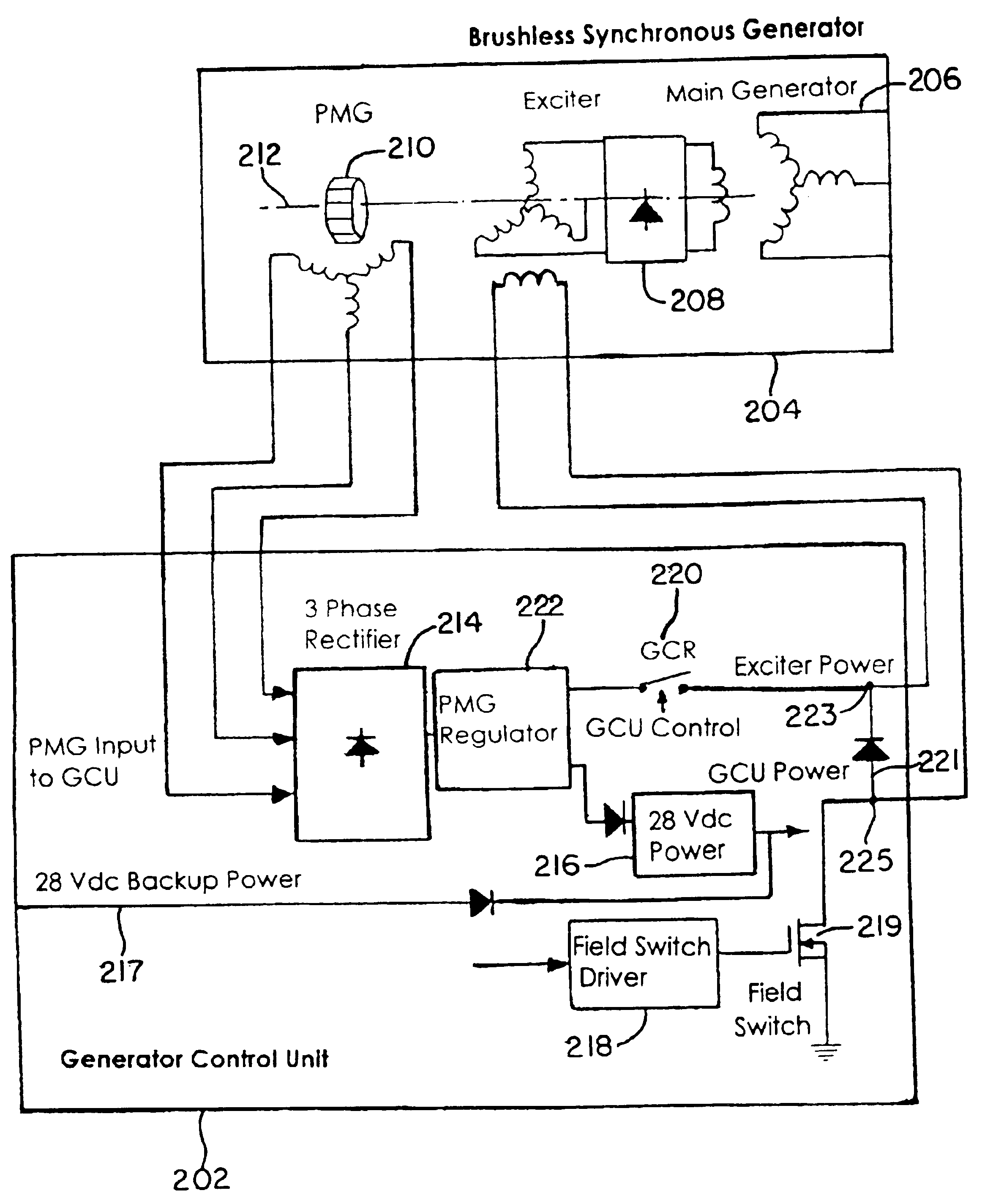
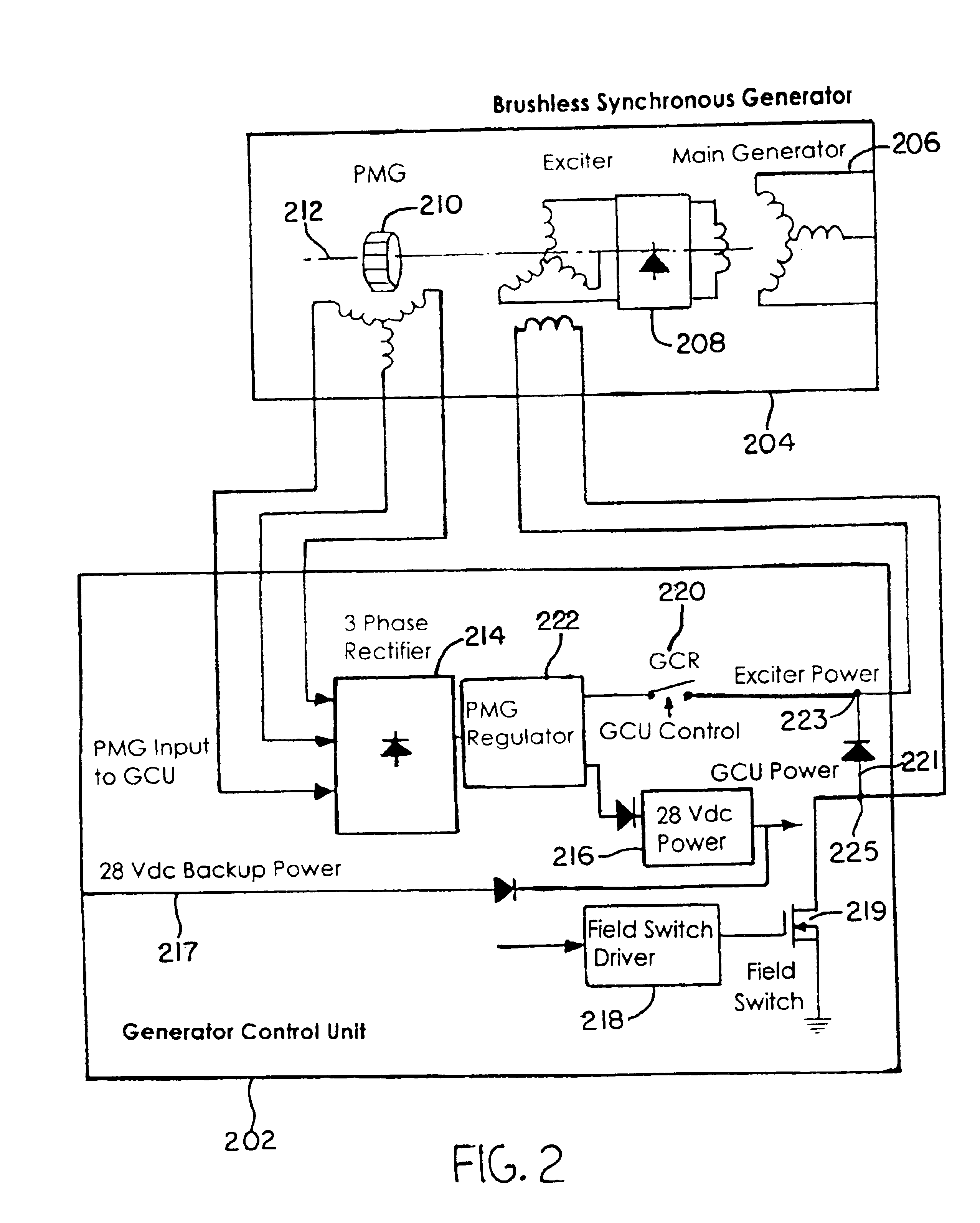
[0023]FIG. 2 illustrates one exemplary embodiment of the present invention. In FIG. 2, a brushless synchronous generator (BSG) 204 includes a PMG 210, an exciter 208 and a main generator 206 that are connected to a rotating shaft 212.

[0024]Also shown in FIG. 2, a generator control unit (GCU) 202 includes a three phase rectifier 214, a PMG voltage regulator 222, a generator control relay (GCR) 220, a GCU power supply 216 with a backup power source 217, a field switch driver 218, a field switch 219 and a free wheeling diode 221 connected between lines 223 and 225. Line 223 connects an output of the PMG regulator 222 to one end of the stator winding of the exciter 208. Line 225 connects the field switch 219 to the other end of the stator winding of the exciter 208. The free wheeling diode 221 modifies exciter ...


PUM


Abstract

A control system regulates power to a brushless synchronous generator (BSG) (204) having a permanent magnetic generator (PMG)(210), an exciter (208) and a main generator (206) connected to a rotating shaft (212). The generator control unit (GCU) (202) includes a three phase rectifier (214), a PMG voltage regulator (222), a generator control relay (GCR)(220), a GCU power supply (216) with a backup power source (217), a field switch driver (218), a field switch (219), and a free wheeling diode (221). The BSG (204) is connected to the GCU (202) by coupling the PMG (210) of the BSG (204) to the three phase rectifier (214) of the GCU (202) and by coupling the exciter (208) of the BSG (204) to the PMG voltage regulator (222) and the field switch driver (218) of the GCU (202) and the PMG voltage regulator (222) regulates the voltage of the PMG (210).

Description

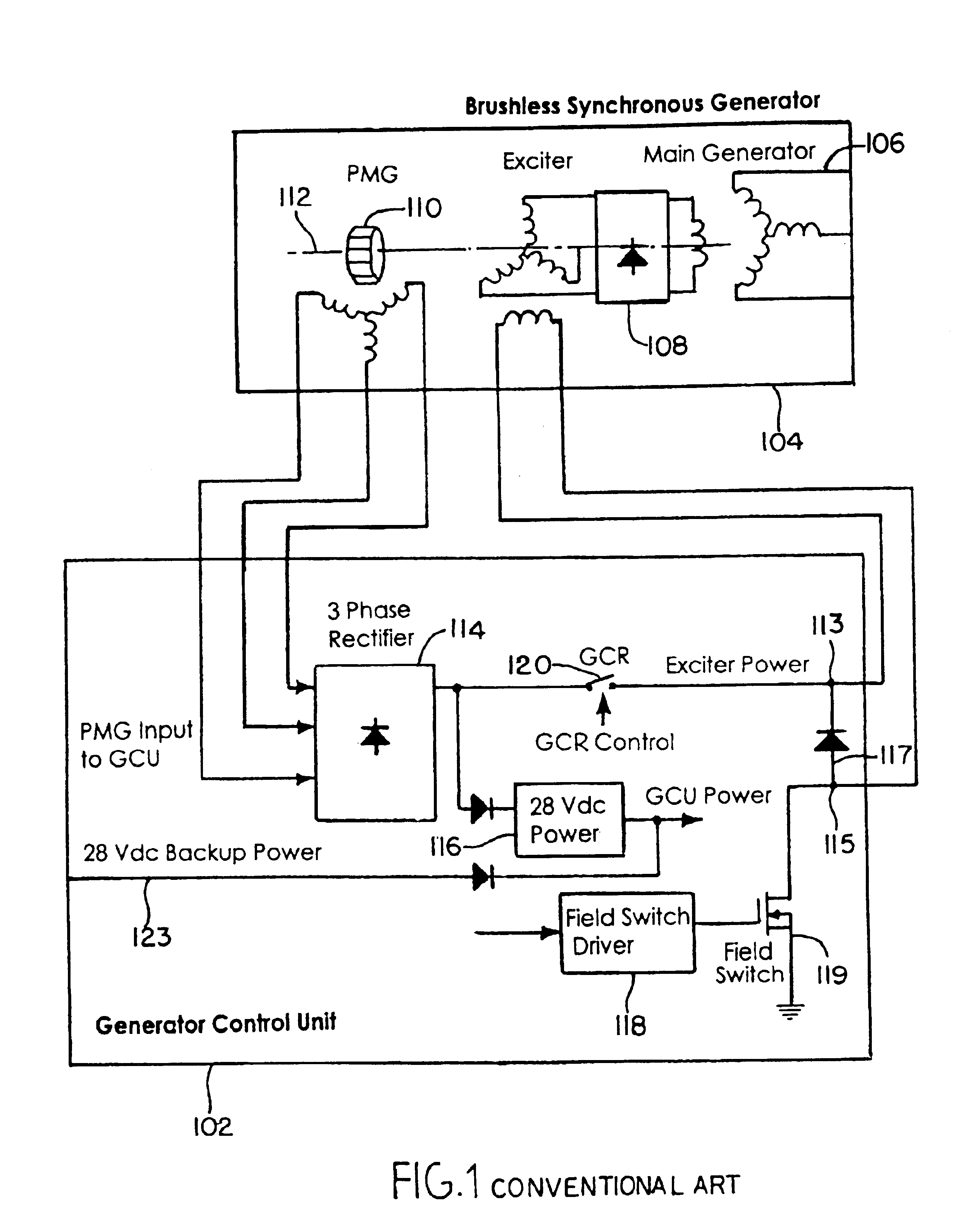
RELATED APPLICATION[0001]This application claims priority under 35 U.S.C. §119(e) of U.S. Provisional Application No. 60 / 335,340 filed on Nov. 2, 2001, the entire contents of which are herein incorporated by reference.FIELD OF THE INVENTION[0002]The present invention relates to a control system for regulating exciter power for a brushless synchronous generator.BACKGROUND OF THE INVENTION[0003]In many aircraft and other airborne systems, AC power is generated from a brushless synchronous generator. FIG. 1 illustrates a conventional configuration of a brushless synchronous generator excitation power arrangement connected to a generator control unit.[0004]A brushless synchronous generator 104 will typically include three types of alternating current (AC) synchronous generators: a main generator 106; an exciter 108; and a permanent magnetic generator (PMG) 110 connected to the same rotating shaft 112. The exciter 108 is used to achieve brushless excitation and the PMG 110 is the power s...

Claims


Application Information

Patent Timeline
IPC IPC(8): H02P9/10H02P9/48H02P9/00H02P9/14H02P9/30
CPCH02P9/105H02P9/48H02P9/305H02P2101/30
Inventor YAO, YUANVLACIC, BORKALI, MONG-HANGHA, MANUEL
Owner HONEYWELL INT INC
Learn More