High performance control server system

a control server and high-performance technology, applied in the field of process control systems, can solve problems such as excessive controller loading, data compression, and poor use of communication resources in the reporting of data, and achieve the effect of increasing flexibility in the process control system

Active Publication Date: 2019-02-21
FISHER-ROSEMOUNT SYST INC
View PDF6 Cites 9 Cited by
  • Summary
  • Abstract
  • Description
  • Claims
  • Application Information

AI Technical Summary

Benefits of technology

[0008]A process control system within one or several process plants includes a centralized or distributed controller farm having several controllers similar to a server farm. The controller farm may include blade servers or rack servers, where each of the controllers in the controller farm is configured to control each of the field devices in a process plant or in several process plants to control the operation of the process plants. In this manner, the controllers are not limited to controlling a predetermined number of field devices located in proximity with each other in a particular portion of a process plant. A single controller within the controller farm may simultaneously control field devices in several portions of the process plant or in different process plants. Additio

Problems solved by technology

Consequently, data which could be useful in troubleshooting and process analysis is often not archived, and if it is collected, the useful information may have been lost due to data compression.
The current techniques used to report the data poorly utilizes communication resources and induces excessive controller loading.
Additionally, due to the time delays in communication and sampling at the historian or silo, the data collection and time stamping is often out of sync wi

Method used


Image

  • High performance control server system
  • High performance control server system
  • High performance control server system

Examples


Embodiment Construction

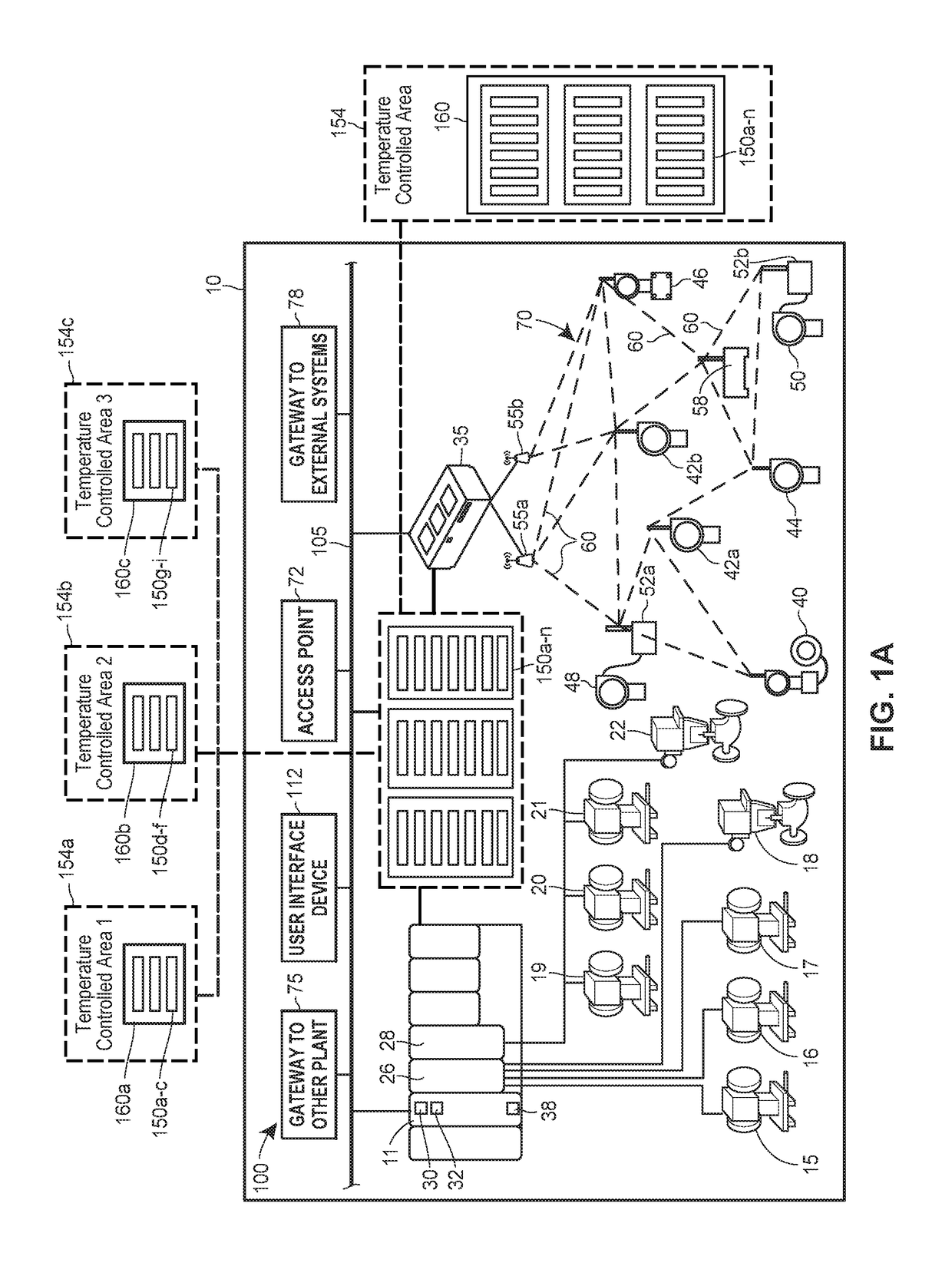
[0014]FIG. 1A is a block diagram of an exemplary process control system 100 operating in a process plant 10. The process control system 100 may include a network backbone 105 providing connectivity directly or indirectly between a variety of other devices. The devices coupled to the network backbone 105 include, in various embodiments, combinations of access points 72, gateways 75 to other process plants (e.g., via an intranet or corporate wide area network), gateways 78 to external systems (e.g., to the Internet), UI devices 112, controllers 150a-n within a controller farm 160, distributed controllers 11, input / output (I / O) cards 26 and 28, wired field devices 15-22, wireless gateways 35, and wireless communication networks 70. The communication networks 70 may include wireless devices 40-58, which include wireless field devices 40-46, wireless adapters 52a and 52b, access points 55a and 55b, and routers 58. The wireless adapters 52a and 52b may be connected to non-wireless field d...


PUM


Abstract

Techniques for controlling the operation of a process plant or several process plants within a process control system using a centralized or distributed controller farm allow for increased flexibility in the process control system. Any of the controllers in the controller farm may be utilized to execute modules corresponding to any of the field devices in one or several process plants. Control modules or other operations may be allocated amongst the controllers distributing the load so that one controller is not performing several operations while others are inactive. Additionally, the controller farm may be located in a temperature controlled room or area in an offsite location from the process plants. In some scenarios, load balancing techniques are performed to distribute the load for the modules equally or at least similarly amongst the controllers.

Description

FIELD OF THE DISCLOSURE[0001]The present disclosure relates generally to process plants and process control systems, and more particularly, to a centralized or distributed controller farm that controls several field devices distributed across one or several process plants.BACKGROUND[0002]Distributed process control systems, like those used in chemical, petroleum, industrial or other process plants to manufacture, refine, transform, generate, or produce physical materials or products typically include one or more process controllers communicatively coupled to one or more field devices via analog, digital or combined analog / digital buses, or via a wireless communication link or network. The field devices, which may be, for example, valves, valve positioners, switches and transmitters (e.g., temperature, pressure, level and flow rate sensors), are located within the process environment and generally perform physical or process control functions such as opening or closing valves, measur...

Claims


Application Information

Patent Timeline
IPC IPC(8): G05B19/418G06F13/40
CPCG06F13/4068G05B19/4185G05B19/418G06F9/5083G05B2219/31457G05B2219/33334Y02P90/02G05B9/03
Inventor ONG, TIONG P.BURR, KENT A.DENISON, DAVID R.SHERRIFF, GODFREY R.LAW, GARYHIEB, BRANDONSMITH, DAVID M.
Owner FISHER-ROSEMOUNT SYST INC
Why Eureka
Try Eureka