
Image comparison system and method

a comparison system and image technology, applied in the field of image processing, can solve the problems of high false match rate, no prior knowledge of the reasons, and object availability, and achieve the effect of eliminating high false match ra

Active Publication Date: 2019-02-21
SIGHTEC ISRAEL LTD
View PDF0 Cites 1 Cited by
  • Summary
  • Abstract
  • Description
  • Claims
  • Application Information

AI Technical Summary

Benefits of technology

The present invention provides an improved method and system for comparing images. The method involves receiving a first image and a second image, identifying tentatively corresponding points in the images, and defining a plurality of image tiles within each image. The tiles are then adjusted in intensity and non-linear functions are applied to each tile. The distance between the tiles is determined, and if the tiles are within the same portion of the image, they are considered observations of the same portion. The system includes a processor and memory for running the method. The technical effects of the invention include improved accuracy and efficiency in image comparison, improved object detection, and improved image quality.

Problems solved by technology

Analyzing and understanding different appearances of an object is an elementary problem in various fields.
The challenge here is to simultaneously cluster the data into multiple linear subspaces and to fit a low-dimensional linear subspace to each set of observations.
Indeed, there are many cases where no prior knowledge on the reasons for the variability in the appearances of an object is available.
As a consequence they frequently result in ambiguous descriptors, which in turn lead to high rates of false matches that need to be eliminated before any further processing can take place.
Such verification procedures require knowledge of the global geometric transformation model (e.g., RANS AC) and are computationally demanding.
Moreover, such global geometric transformation model is often unknown, or difficult to estimate.

Method used


Image

  • Image comparison system and method
  • Image comparison system and method
  • Image comparison system and method

Examples


Embodiment Construction

[0028]Before explaining at least one embodiment of the invention in detail, it is to be understood that the invention is not limited in its application to the details of construction and the arrangement of the components set forth in the following description or illustrated in the drawings. The invention is applicable to other embodiments or of being practiced or carried out in various ways. Also, it is to be understood that the phraseology and terminology employed herein is for the purpose of description and should not be regarded as limiting.

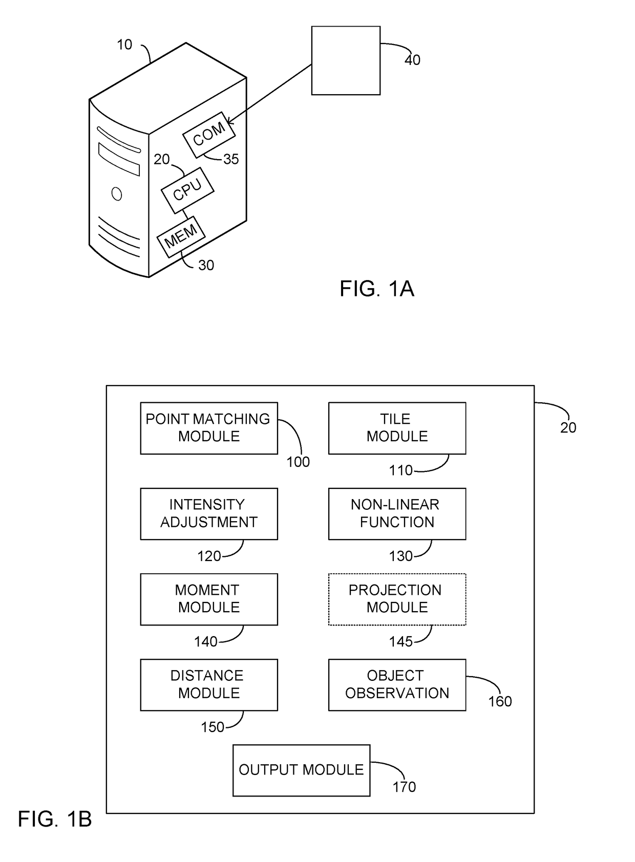
[0029]FIG. 1A illustrates a high level schematic diagram of an image comparison system 10, system 10 comprising: a processor 20; a memory 30; and a communication module 35. In one embodiment, processor 20 is arranged to operate responsive to instructions stored on memory 30. Communication module 35 is in communication with an image input source 40. In one embodiment, image input source 40 is a user input device, such as an imaging device. In a...


PUM


Abstract

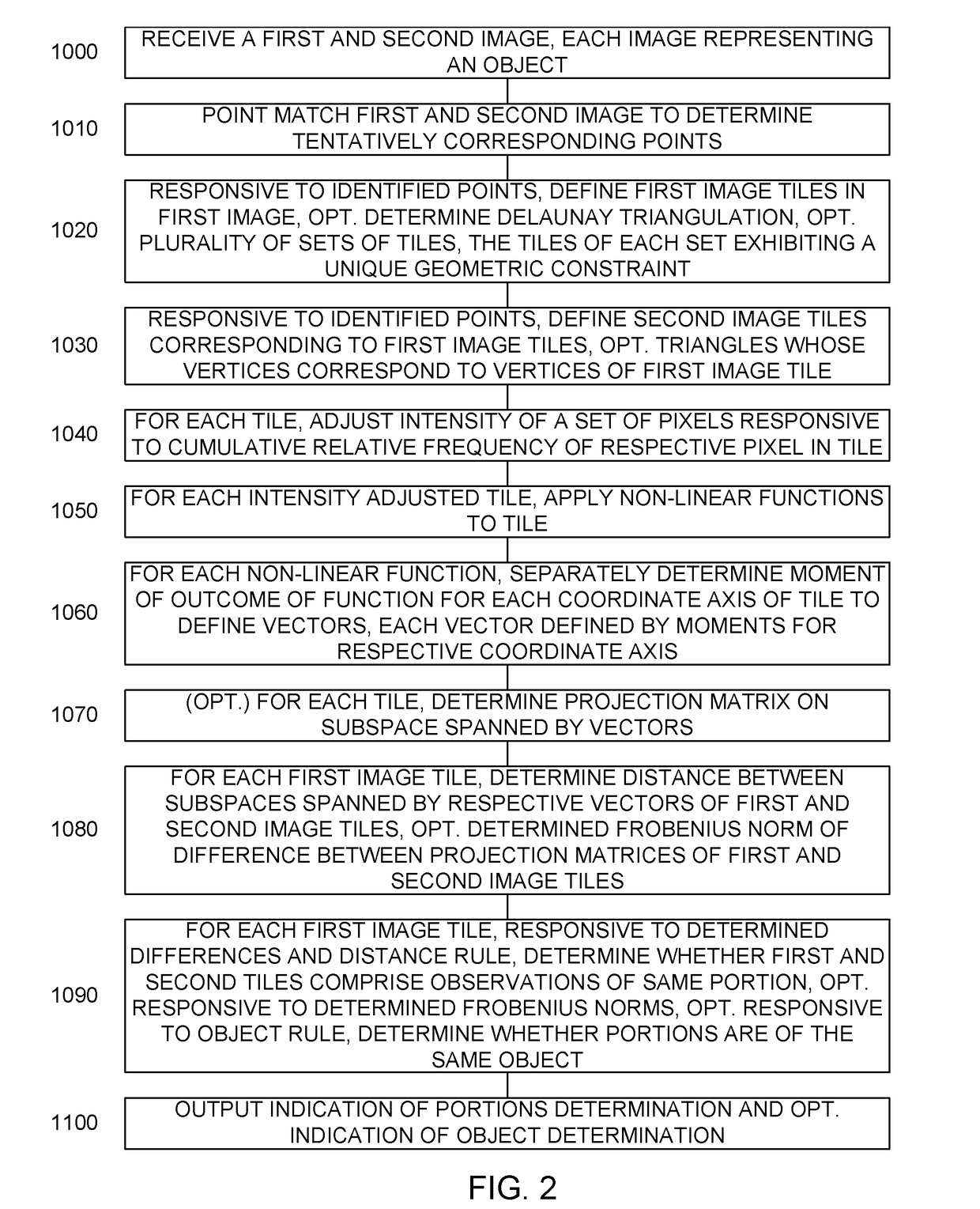
An image comparison method constituted of: receiving images; point matching the images to identify tentatively corresponding points; responsive to the identified points, defining a plurality of first image tiles within the first image; defining a plurality of second image tiles within the second image, each corresponding to a respective first image tile; adjusting the intensity of a set of pixels responsive to the cumulative relative frequency of the respective pixel intensity within the respective tile; for each tile, applying a plurality of non-linear functions; for each function, separately determining a moment of the outcome of the respective non-linear function for each axis of the respective tile; for each first image tile and corresponding second image tile, determining a distance between the subspaces spanned by moment vectors; and responsive to determined distances, determining whether respective first and second image tiles comprise observations of the same portion.

Description

CROSS-REFERENCE TO RELATED APPLICATIONS[0001]This application claims priority from U.S. provisional application Ser. No. 62 / 308,751, filed Mar.15, 2016 and entitled “GEOMETRY AND RADIOMETRY INVARIANT MATCHED MANIFOLD DETECTION TRACKING AND RECOGNITION SYSTEM AND METHOD”, the entire contents of which are incorporated herein by reference.TECHNICAL FIELD[0002]The present invention relates generally to the field of image processing, and in particular to an image comparison system and method.BACKGROUND[0003]U.S. Pat. No. 7,406,197, issued Jul. 29, 2008 to Francos et al., and U.S. Pat. No. 7,865,02, issued Jan. 4, 2011 to Francos et al., the entire contents of each which is incorporated herein by reference, are addressed to a parametric estimation of multi-dimensional homeomorphic transformations. U.S. Pat. No. 8,275,204, issued Sep. 25, 2012 to Kovalsky et al., the entire contents of which are incorporated herein by reference, is addressed to an estimation of joint radiometric and geomet...

Claims


Application Information

Patent Timeline
Patent Type & Authority Applications(United States)
IPC IPC(8): G06K9/62
CPCG06K9/6211G06K9/6215G06T7/248G06T2207/20021G06K2009/6213G06V10/759G06F18/22
Inventor FRANCOS, JOSEPHHAGEGE, RAMI
Owner SIGHTEC ISRAEL LTD
Learn More