Electromagnetic induction device and method for manufacturing same

Inactive Publication Date: 2019-02-21
BOLYMEDIA HLDG
View PDF8 Cites 2 Cited by
  • Summary
  • Abstract
  • Description
  • Claims
  • Application Information

AI Technical Summary

Benefits of technology

[0007]With regard to the electromagnetic induction device according to the present disclosure, wrapping the coils by the magnetic cover composed of a plurality of magnetic units may, on the one hand, substantially enclose the coils, preventing magnetic flux leakage to a maximum extent, and on the other hand, since dividing surfaces between magnetic units are disposed along a magnetic flux loop, no air gap is generated in the magnetic flux loop, th

Problems solved by technology

Such structure may lead to a large magnetic flux leakage for the transformer, causing energy loss and radiation damage.
However, the configuration of such transformer may

Method used


Image

  • Electromagnetic induction device and method for manufacturing same
  • Electromagnetic induction device and method for manufacturing same
  • Electromagnetic induction device and method for manufacturing same

Examples


first embodiment

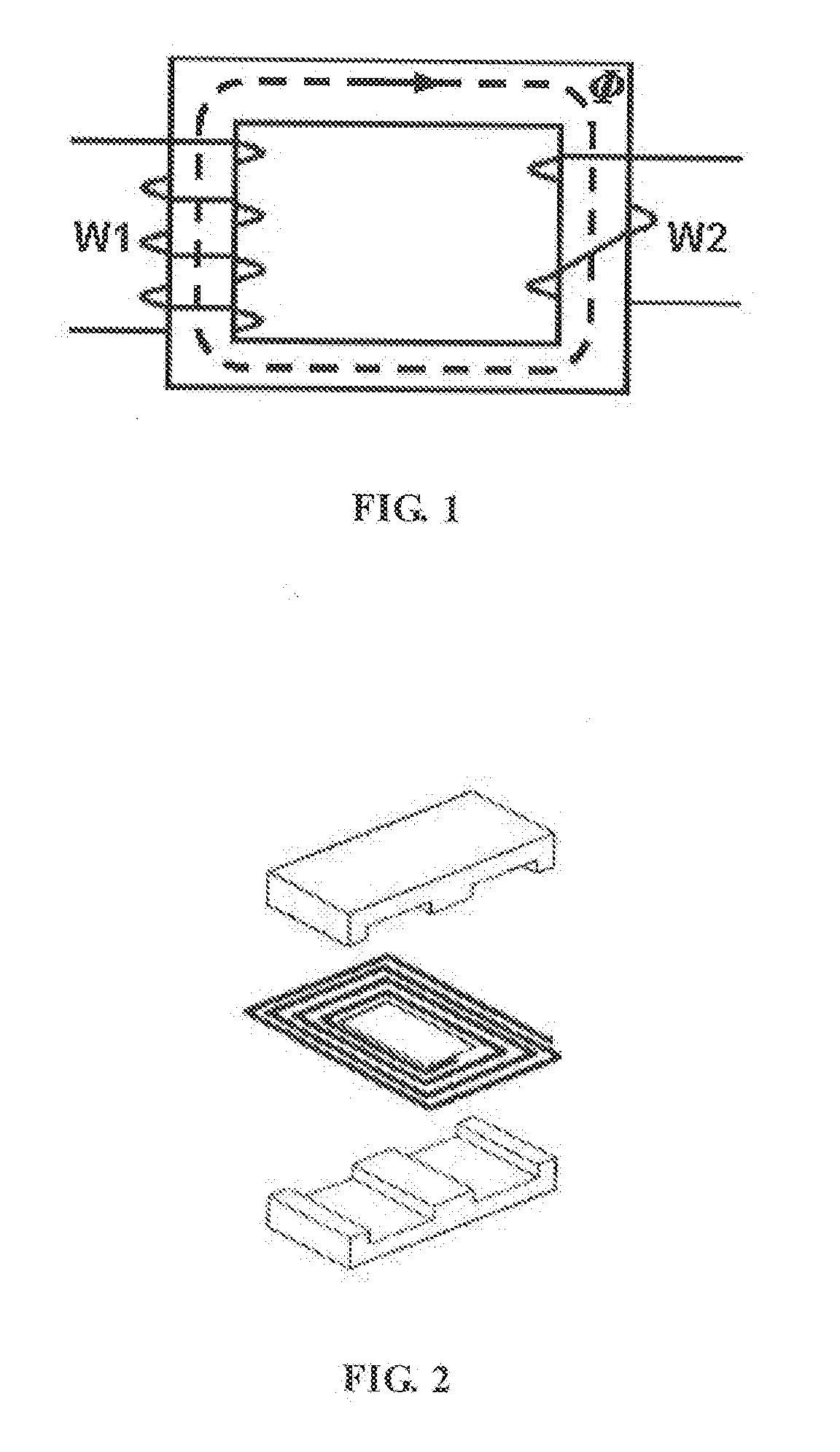
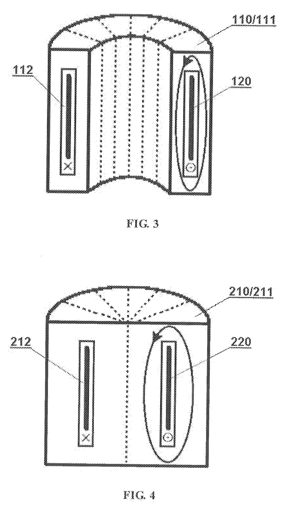
[0026]FIG. 3 shows an embodiment of electromagnetic induction device in accordance with the present disclosure. The electromagnetic induction device may include a magnetic cover 110 and coils 120.

[0027]The cavity inside the magnetic cover is an annular one 112, and its overall shape may be doughnut-shaped, elliptical ring-shaped, rectangular, polygonal and the like. The normal section of the hollow portion of the cavity may be rectangular or round, or a relatively random shape as long as the coils can be wrapped therein. Preferably, the cavity should wrap the coils as closely as possible, and its shape can therefore substantially con form to the shape of the cross section of the coils.

[0028]In this embodiment, the magnetic cover is divided into two magnetic units having the same shape by a dividing surface substantially perpendicular to the center line of the annular cavity. For the convenience of demonstration, only one magnetic unit 111 is illustrated in FIG. 3, and therefore FIG....

second embodiment

[0033]FIG. 4 shows another embodiment of electromagnetic induction device in accordance with the present disclosure. The electromagnetic induction device may include a magnetic cover 210 and coils 220.

[0034]The structure of this embodiment is similar to that of the first embodiment. The magnetic cover has an annular cavity 212 inside, and is divided into two magnetic units having the same shape by a dividing surface perpendicular to the center line of the annular cavity. For the convenience of demonstration, only one magnetic unit 211 is illustrated in FIG. 4. The difference between this embodiment and the first embodiment is that, the magnetic cover in the first embodiment is a hollow cylinder, while the magnetic cover in this embodiment is a solid (except for the annular cavity 212) cylinder. The division for the magnetic cover and the configuration of the coils can be referred to the first embodiment, which will not be repeated herein.

[0035]In other embodiments, the magnetic cove...

third embodiment

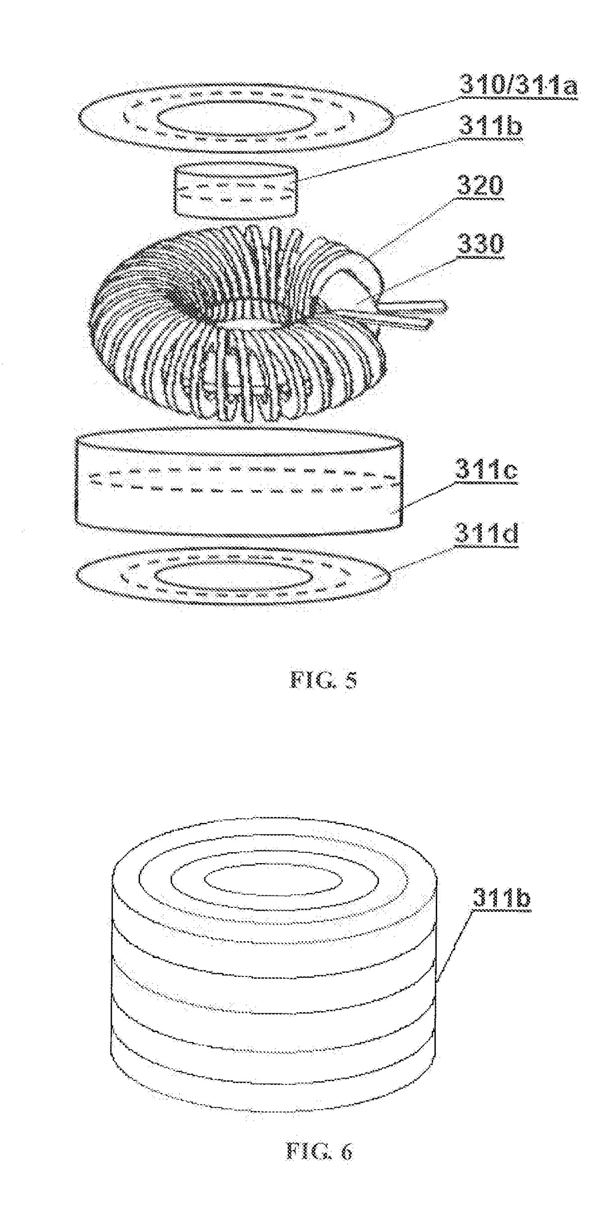
[0036]FIG. 5 shows still another embodiment of electromagnetic induction device in accordance with the present disclosure. The electromagnetic induction device may include a magnetic cover 310 and coils 320.

[0037]The cavity inside the magnetic cover 310 is an annular cavity. The magnetic cover may be divided into two or more magnetic units by a dividing surface substantially parallel to the annulus of the annular cavity.

[0038]In this embodiment, the magnetic cover 310 is divided into four magnetic units, that is, a magnetic unit 311a as a top cap, a magnetic unit 311b (which may be a hollow cylinder or a solid cylinder) as the inner wall of the annular cavity, a magnetic unit 311c as the outer wall of the annular cavity, and a magnetic unit 311d as a bottom cap. The broken line in FIG. 5 represents the magnetic flux loop.

[0039]The coils 320 are formed by a wire winding around its axis, and the axis of the coils may be extended in a direction substantially conforming to the extension...


PUM


Abstract

Disclosed are an electromagnetic induction device and a method for manufacturing the same. The device comprises a magnetic cover (110) and at least one set of coils (120). The magnetic cover (110) consists of two or more magnetic units (111), and a closed magnetic flux loop can be formed within each magnetic unit (111). The magnetic units (111) are joined together to form a substantially closed integrated body having at least one cavity (112) therein, and dividing surfaces between the magnetic units (111) are disposed substantially along the magnetic flux loop without interrupting the magnetic flux loop. The coils (120) are placed in the cavity (112) formed by the magnetic cover (110), electrodes of the coils (120) are led out of the magnetic cover (110), and the magnetic flux loop in the magnetic cover (110) is formed after energization of the coils (120). The electromagnetic induction device of the present invention can substantially close coils, preventing magnetic flux leakage to a maximum extent. Further, since dividing surfaces between magnetic units are disposed along a magnetic flux loop, no air gap is generated in the magnetic flux loop, thereby effectively decreasing magnetic resistance.

Description

TECHNICAL FIELD[0001]The present disclosure relates to electronic or electric devices, and in particular, to electromagnetic induction devices and manufacturing methods thereof.BACKGROUND OF THE INVENTION[0002]Generally, weak-current equipment (which operates in lower voltage and lower current) is referred to as an electronic device, while heavy-current equipment (which operates in higher voltage and higher current) is referred to as an electric device. Many electronic and electric devices, such as inductors, transformers and the like, operate based on electromagnetic induction effect.[0003]An electromagnetic induction device may typically include a magnetic core and a coil. In an example shown in FIG. 1, a single-phase transformer has two sets of coils, i.e. a primary winding W1 and a secondary winding W2. When an alternating current is applied to electrodes at both ends of W1, an alternating magnetic field Φ is generated on a magnetic core wrapped by the winding. The magnetic fiel...

Claims


Application Information

Patent Timeline
IPC IPC(8): H01F27/34H01F27/24H01F27/28H01F1/03H01F1/147H01F1/34H01F41/061
CPCH01F27/346H01F27/24H01F27/2804H01F1/0315H01F1/14741H01F1/344H01F41/061H01F17/06H01F3/10H01F27/36H01F27/366H01F27/02H01F27/26
Inventor HU, XIAOPING
Owner BOLYMEDIA HLDG
Why Eureka
Try Eureka