Magnetic resistance type driving belt conveyor and driving control method

A driving belt, magnetoresistive technology, applied in the direction of conveyor control device, conveyor, conveyor objects, etc., can solve the problems of reduced conveyor belt tension requirements, many power transmission components, and power transmission chain length, etc. Strong, prevent magnetic leakage phenomenon, the effect of uniform force

Inactive Publication Date: 2020-08-07
福建龙净环保智能输送工程有限公司
View PDF7 Cites 0 Cited by
  • Summary
  • Abstract
  • Description
  • Claims
  • Application Information

AI Technical Summary

Problems solved by technology

[0008] The reluctance drive belt conveyor of the present invention includes a coil winding set on the conveyor belt, and the conveyor belt is provided with iron cores at intervals along the warp direction. By controlling the current in a specific coil winding, the iron core is driven by force to convey The belt does not need a separate motor to drive the drum to rotate like the existing technology, and then transmits the kinetic energy of the drum to the conveyor belt, which solves the problem of transmission failure such as conveyor belt slippage and difficulty in starting when overloaded or loaded, and the power transmission chain length, power There are many transmission parts, and there is no need to transmit power through friction, and the requirements for the tension of the conveyor belt are reduced, so that the conveyor belt with lower strength can be selected in practical applications, which reduces the investment cost and prolongs the service life of the conveyor belt.

Method used


Image

  • Magnetic resistance type driving belt conveyor and driving control method
  • Magnetic resistance type driving belt conveyor and driving control method
  • Magnetic resistance type driving belt conveyor and driving control method

Examples


Embodiment Construction

[0045] In order to enable those skilled in the art to better understand the technical solutions of the present invention, the present invention will be further described in detail below in conjunction with the accompanying drawings and specific embodiments.

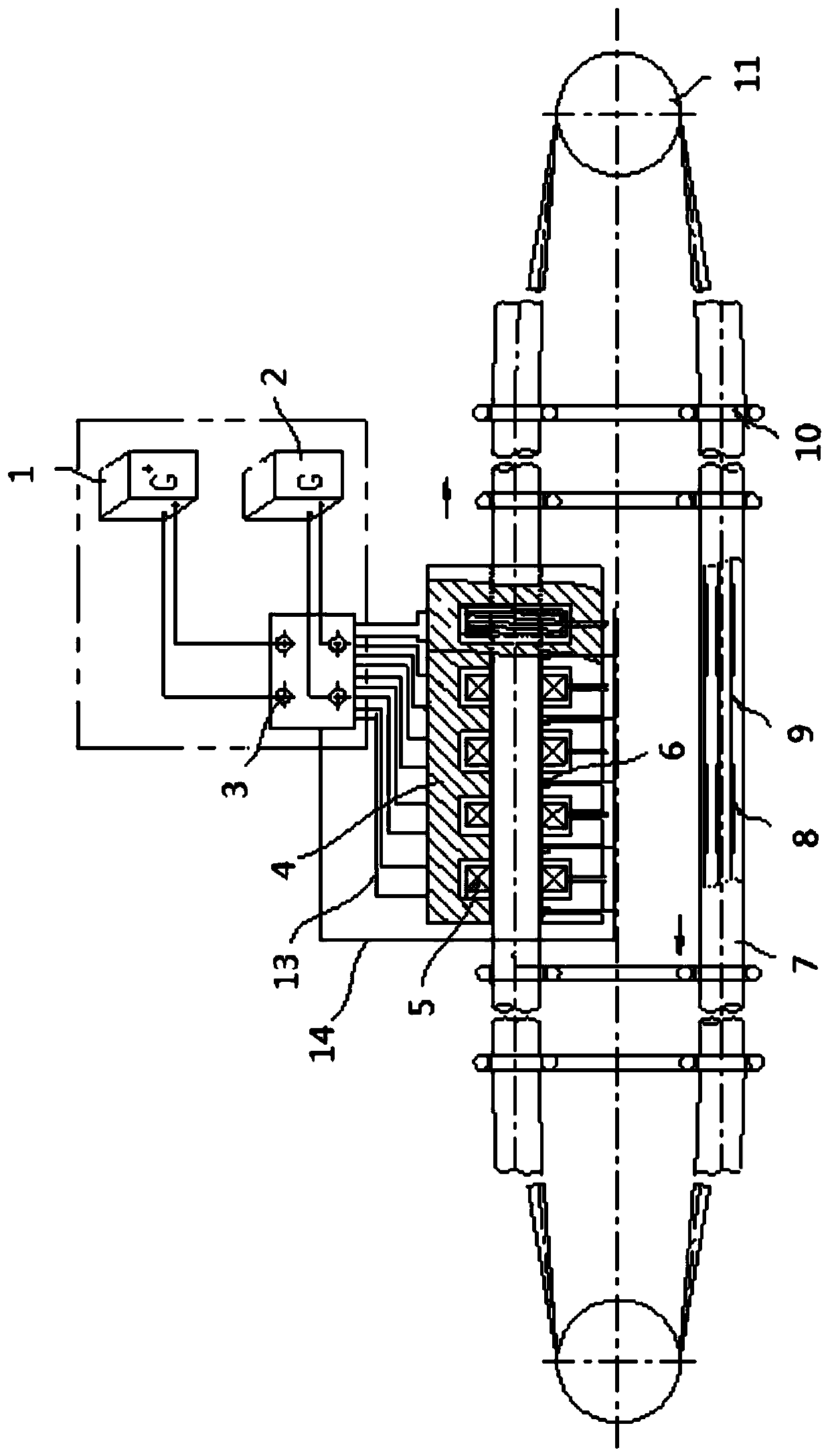
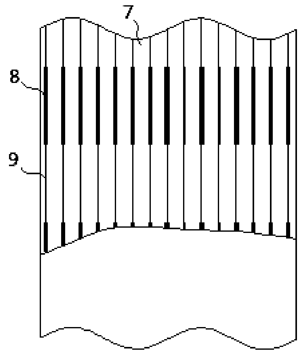
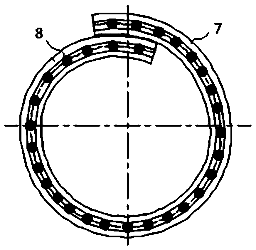
[0046] Herein, the central point of the coil winding 5 along the axial direction is the "dead point" of the coil winding 5; the moving direction along the conveyor belt 7 is the "longitudinal direction"; figure 1 and Figure 6 The direction shown by the arrow in the middle corresponds to the direction of motion of the conveyor belt 7, the direction consistent with the direction of motion of the conveyor belt 7 is "front", and the direction opposite to the direction of motion of the conveyor belt 7 is "back".

[0047] Please refer to Figure 1 to Figure 5 , understand the structural representation of the conveyor belt 7 and the driving device in the reluctance drive belt conveyor of the present invention, figure 1 It is ...


PUM


Abstract

The invention discloses a magnetic resistance type driving belt conveyor. The magnetic resistance type driving belt conveyor comprises a driving device, a conveying belt (7) and rollers (11), whereinthe conveying belt (7) is wound between the rollers (11) at two ends, the conveying belt (7) is provided with at least one set of iron cores, and the set of iron cores are distributed at intervals ina warp direction of the conveying belt (7); the driving device comprises a power supply part and a stator which are connected with each other, the stator comprises coil windings (5), the conveying belt (7) is sleeved with the coil windings (5), and the coil windings (5) are uniformly arranged in the warp direction of the conveying belt (7), and the power supply part is used for providing current for the coil windings (5); and the iron cores can drive the conveying belt (7) under the action of the coil winding (5). The invention further provides a driving control method of the magnetic resistance type driving belt conveyor. The iron cores are stressed to drive the conveying belt (7) by controlling the magnitude of current in the coil windings (5), and the problems that in the prior art, theconveying belt slides in a transmission mode, starting is difficult, and the number of power transmission components is large are solved.

Description

technical field [0001] The invention relates to the technical field of power-driven conveyors, in particular to a reluctance-driven belt conveyor and a drive control method. Background technique [0002] Belt conveyor is a kind of long history, economical, applicable and modern conveying machinery. In recent years, it has gradually shown the development trend of long distance, high belt speed, large capacity and intelligence. [0003] For traditional belt conveyors, the required driving force is generally transmitted through the friction between the transmission roller and the conveyor belt. The head and tail drive are the main ones. The existing magnetic levitation belt conveyor uses the magnetic attraction between the magnetic roller and the clamping magnetic conveyor belt to replace the friction force to provide the driving force for the magnetic conveyor belt. At the same time, the clamping magnetic conveyor belt and the magnetic force There is a repulsive force between...

Claims


Application Information

Patent Timeline
Patent Type & Authority Applications(China)
IPC IPC(8): B65G23/18B65G43/00
CPCB65G23/18B65G43/00
Inventor 施锐熊汉辉廖辉陈超汉彭锐丹
Owner 福建龙净环保智能输送工程有限公司
Why Eureka
Try Eureka