Joint seal system with shaped barrier and wings

a seal system and joint technology, applied in the field of joint seal system with shaped barrier and wings, can solve the problems of sealing system failure, thick and inflexible seals, and joints that are subject to damage,

Active Publication Date: 2019-02-28
SCHUL INT COMPANY
View PDF21 Cites 38 Cited by
  • Summary
  • Abstract
  • Description
  • Claims
  • Application Information

AI Technical Summary

Benefits of technology

[0020]The present invention thus provides redundancy, and potentially a status notification of change in critical joint conditions in situ for water-resistant, fire-resistant and / or roof expansion joints.

Problems solved by technology

Moreover, these joints are subject to damage over time.
Most damage is from vandalism, wear, and environmental factors, where the seal may become thick and inflexible or are fragile.
These systems, however, often fail due to the differences in compression and expansion of the various constituents, or the lack of bonding between layers, or because the system is directed to a particular purpose, such as water-resistance, but is exposed to fire, causing the seal system to fail and permit water to migrate behind the seal system.
Vandalism, normal wear and environmental exposure can change or defeat the properties of the exposed surface coating or membrane.
There is also the case where the best material or barrier may not be used because it is aesthetically unpleasing or cannot easily be colored.
Additionally, in some cases the movement of the joint may be limited, sometimes to only twenty-five percent (+ / −25%) in compression and expansion, for a total movement of only fifty percent (50%).
Additionally, for pre-compressed joint sealants with a silicone face, a myriad of potential failure risks exists.
Typically, the surface coating of these joints is relatively thin and can be damaged.
Where joint substrate is irregular, a complete seal at the joint face might not be accomplished.
Water intrusion from behind the joint face could find its way into or past the joint sealant and may result in poor performance or a leak, particularly problematic is products that rely on water-based intumescent surface coating, which can revert or delaminate if subject to continuous moisture.
Pre-compressed or compressible joint sealants without an elastomer coating or surface impregnation often have similar limitations.
If the foam sealant systems designed based on laminations (acrylics or strong pressure sensitive adhesives in particular) are parallel to the joint substrate, they tend to separate over time, losing their sealant properties.
If there is any damage to the thin (60 mil or less coating) the system will not perform as designed.
This is further complicated by the use of the multiple laminations that if separated would let rater, smoke or fire penetrate the system.
Failure of any of these listed shortcomings will reduce the useful lifespan of the joint sealant.
Because the primary sealant is always subject to adhesive, cohesive and environmental forces and therefore tends to wear out over time and leak, it is a good practice to have redundant systems.

Method used


Image

  • Joint seal system with shaped barrier and wings
  • Joint seal system with shaped barrier and wings
  • Joint seal system with shaped barrier and wings

Examples


first embodiment

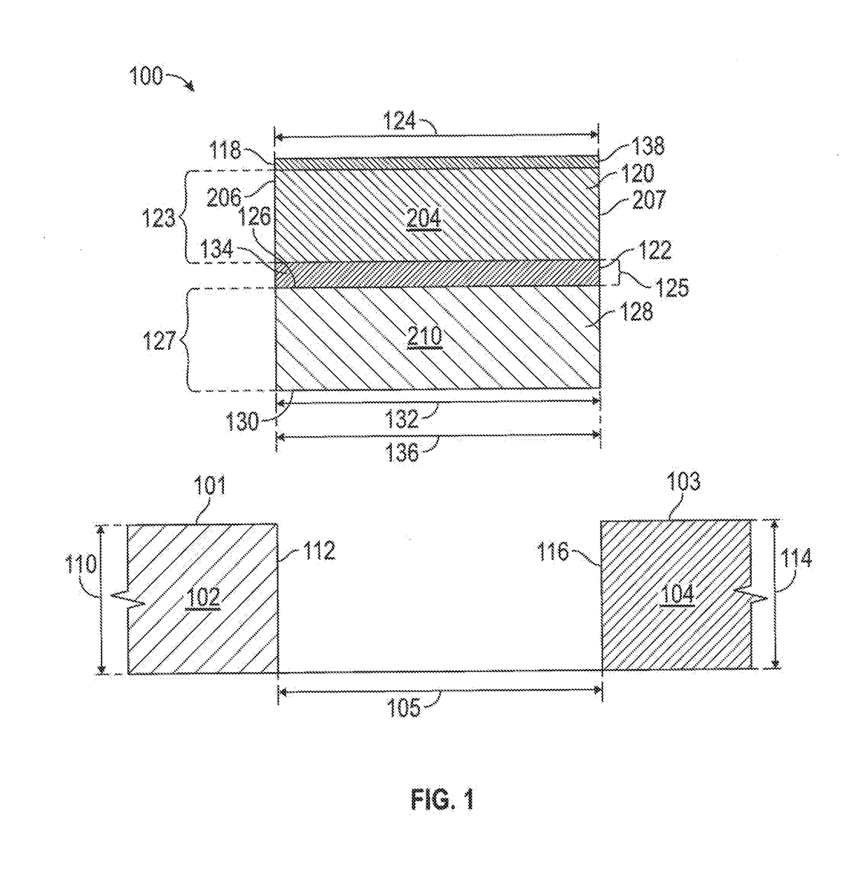
[0078]Referring to FIG. 1, the joint seal 100 may further include an elastomer 138, such as silicone adhered to the first body top 118 and / or to the bottom of the bottom-most layer or body 128, the second body bottom 130 in the Alternatively, as illustrated in FIG. 9 the joint seal 100 may alternatively include a resilient flexible surface barrier 902, such as one or more layers of a synthetic rubber roofing membrane, including ethylene propylene diene terpolymer (EPDM), bonded or adhered to the first body top 118, such as by heating of materials or by adhesive. The surface bather 902 may include at its distant end 904 an upper elongate appendage 906 and, below and generally coplanar, a lower elongate appendage 908, formed, for example, by the lack of adhesive between two adjacent layers or bodies and by cutting a single layer or body along its edge 910. The surface barrier 902 may lap over or about the membrane of a roofing system to provide an effective seal. The surface barrier ...

embodiment 400

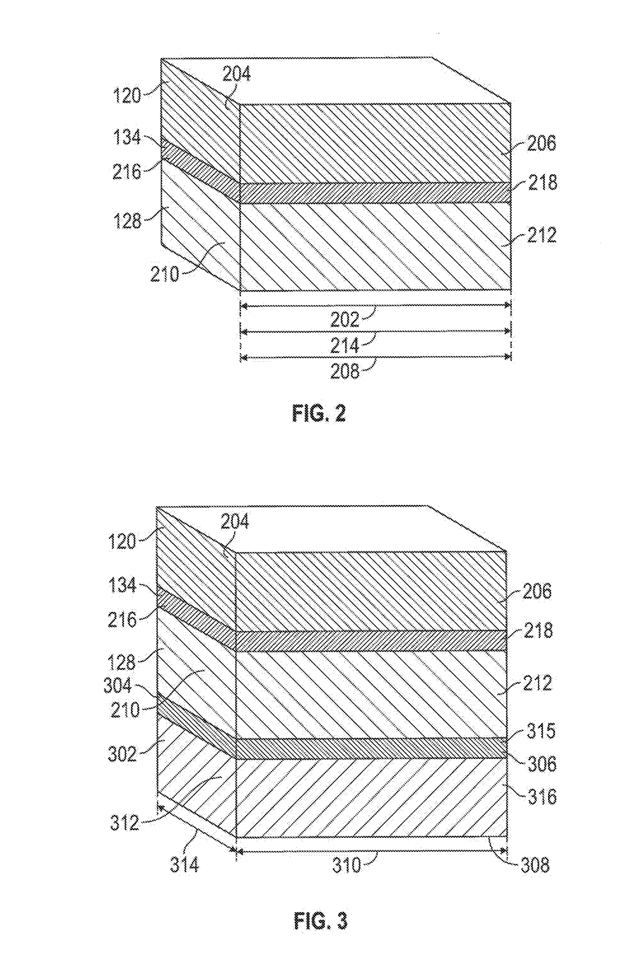
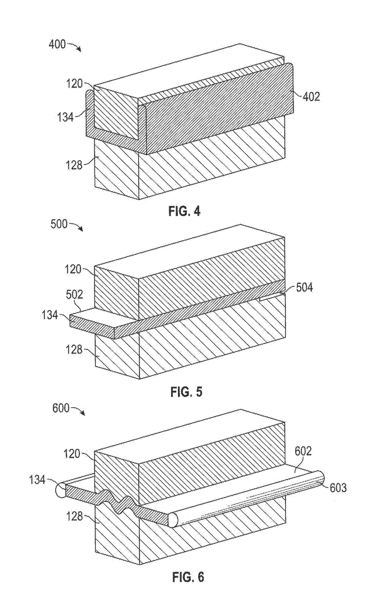
[0086]Referring now to FIG. 10, the barrier 134 of the embodiment of FIG. 3 may be provided with a barrier width 1002 which is greater than the first body width 124 and the second body width 132 to provide a first wing 1006 and a second wing 1008. The second barrier 304 may have a second barrier width 1004, greater than each of the second body width 132 and the third body width 314. Each wing 1006, 1008 may include at its distant end 1010, 1012 an upper elongate appendage 1014, 1016 and, essentially co-planar and below, a lower elongate appendage 10181020, formed, for example, by the lack of adhesive between two adjacent layers or bodies and by cutting a single layer along an edge 1022. Such appendages may lap over or about a roofing system to provide an effective seal. Referring now to FIG. 4, in an alternative embodiment 400, the joint seal includes a first body of compressible foam 120, a second body of compressible foam 128, and a barrier 134 adhered to both the first body of co...

embodiment 700

[0093]Referring now to FIG. 7, in another further alternative embodiment 700, the barrier 134 may be of a narrower width than the first body 120 and the second body 128. Thus, the barrier 134 may terminate short of the edge of the first body 120 and the second body 128. This variation allows for the benefit of the different foams for the first body 120 and the second body 128 and also allows for the barrier 134 to accept less compression while still providing its intended properties.

[0094]In connection with each embodiment, cutting the first body 120 and the second body 128 into interlocking (male / female) sections using a radius of at least 0.1875 niches permits a thicker barrier 134 to be used without bowing or deformation of the foam, a benefit previously available only when a thin barrier 134 might be used. In the prior art, use of a random accordion style would cause the barrier 134 to fatigue after cycling.

[0095]An example is a joint seal using two different fire-rated foams as...


PUM

PropertyMeasurementUnit
depthsaaaaaaaaaa
widthaaaaaaaaaa
thicknessaaaaaaaaaa

Abstract

An expansion joint seal proving a flexible barrier therethrough in a concave shape with a first body of compressible foam on one side and a second body of compressible foam on the other side, where the barrier extends laterally from the first body and second body and may be used to protect the sides of the expansion joint seal or may be used to provide contact on the surface of each adjacent substrate.

Description

CROSS-REFERENCE TO RELATED APPLICATIONS[0001]This application is a continuation-in-part U.S. patent application Ser. No. 15 / 189,671 for Joint seal system, filed Jun. 22, 1016, which i a continuation of U.S. patent application Ser. No, 14 / 630,125, Joint seal system, filed Feb. 24, 2015, issued as U.S. Pat. No. 9,404,581 on Aug. 2, 2015 which is incorporated herein by reference and claims the priority of U.S. Provisional Patent Application No. 61 / 940,311, filed Feb. 28, 1014 for “Joint Seal System,” which is incorporated herein by reference.STATEMENT REGARDING FEDERALLY SPONSORED RESEARCH OR DEVELOPMENT[0002]Not Applicable.BACKGROUNDField[0003]The present disclosure relates generally to systems for creating a durable seal between adjacent panels, including those which may be subject to temperature expansion and contraction or mechanical shear. More particularly, the present disclosure is directed to providing an integral multilayer joint seal system against one or more of water, fire,...

Claims


Application Information

Patent Timeline
Patent Type & Authority Applications(United States)
IPC IPC(8): F16J15/10B32B3/02F16J15/06B32B5/32B32B7/12B32B15/04B32B37/02B32B38/00
CPCB32B2255/102B32B15/046B32B2307/3065B32B2307/54B32B2307/7265B32B2307/7246B32B2307/7242B32B2305/022B32B38/0004B32B37/02F16J15/065F16J15/104B32B7/12B32B3/02B32B5/32F16J15/108B32B2581/00F16J15/022F16J15/064E04B1/681
Inventor ROBINSON, STEVEN R.ISKE, BRIAN J.ISKE, DEREK J.FIORILLA, NICHOLAS A.BALLOU, JOEL R.
Owner SCHUL INT COMPANY
Why Eureka
Try Eureka