Method and apparatus for determining lubricant contamination or deterioration in an engine

a technology of lubricant contamination and deterioration, which is applied in the direction of machines/engines, turbines, instruments, etc., can solve the problems of reducing the effectiveness of oil, clogging or damage parts of the engine, and reducing the effectiveness or damage of the engin

Active Publication Date: 2019-02-28
GENERAL ELECTRIC CO
View PDF4 Cites 10 Cited by
  • Summary
  • Abstract
  • Description
  • Claims
  • Application Information

AI Technical Summary

Problems solved by technology

Often, heightened temperatures of the lubricant can lead to oil slag, varnish or coking, which can reduce effectiveness of the oil or can clog or damage portions of the engine.
Similarly, the lubricant can bec

Method used


Image

  • Method and apparatus for determining lubricant contamination or deterioration in an engine
  • Method and apparatus for determining lubricant contamination or deterioration in an engine
  • Method and apparatus for determining lubricant contamination or deterioration in an engine

Examples


Embodiment Construction

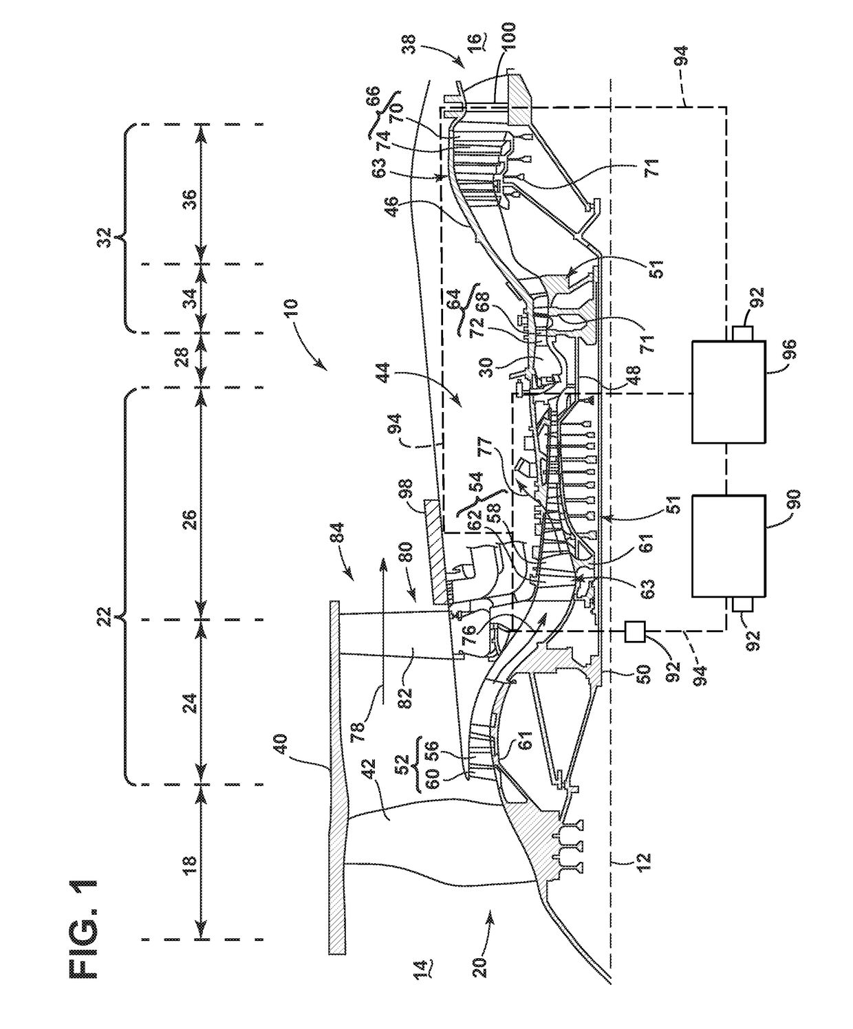
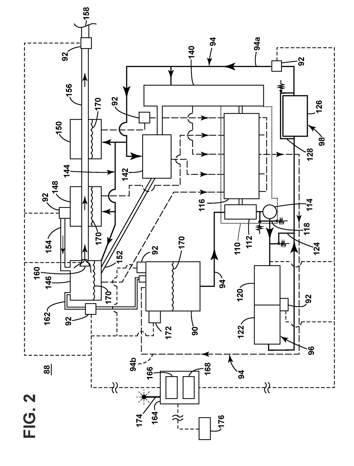
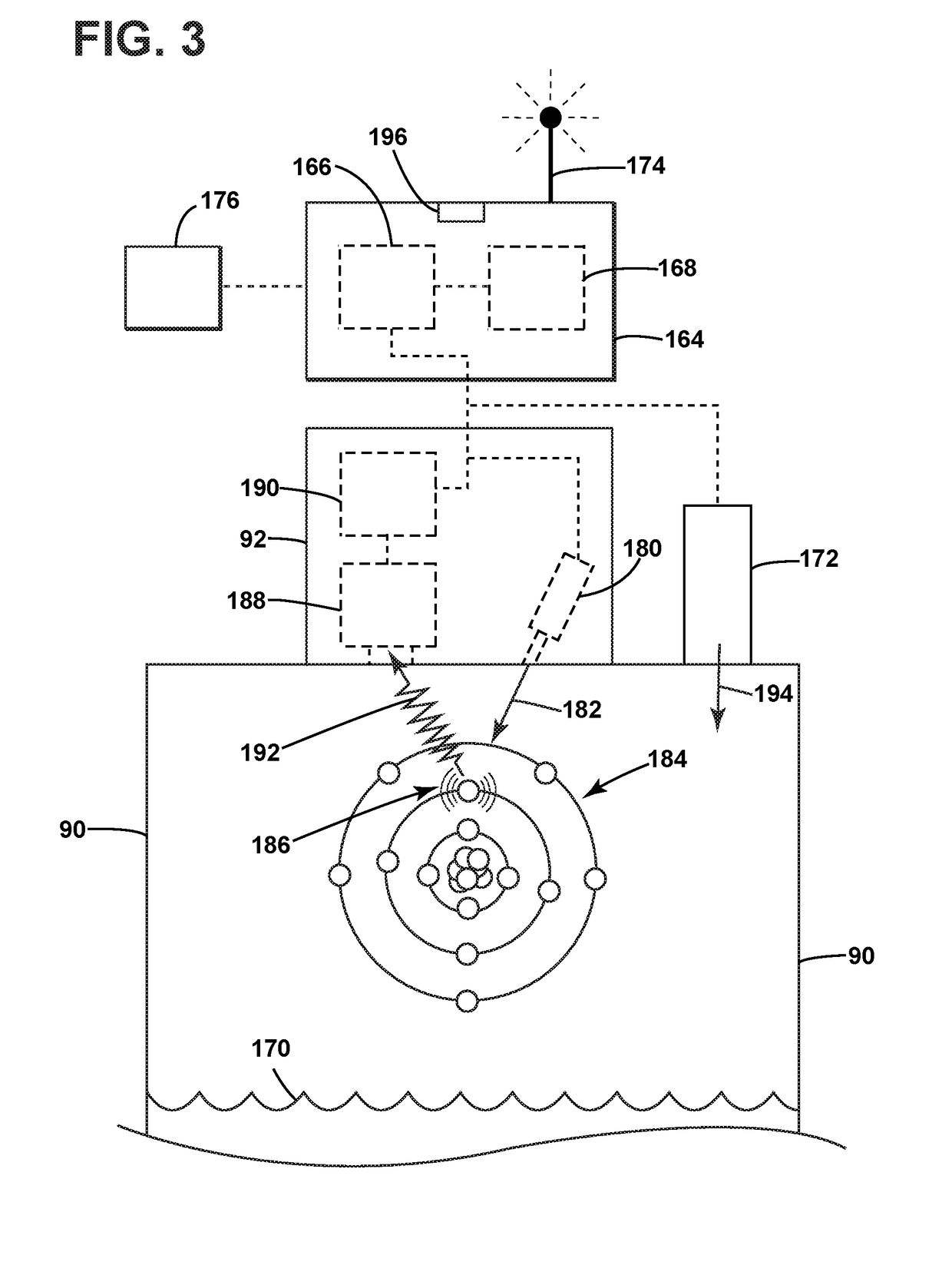
[0014]Aspects of the disclosure described herein are directed to a method and apparatus for sensing and measuring aspects of lubricant within a turbine engine. Measurements can be made within the engine in real time, as well as between operations and while the engine is on-wing. The real-time measurements can provide for a multitude of readings for different aspects of the lubricant. The different readings can be interpreted and compared against baseline or threshold values to determine different types of contamination for the lubricants, which can provide for improved maintenance and can minimize the negative effects of lubricant contamination. For purposes of illustration, the present disclosure will be described with respect to a gas turbine engine for an aircraft. It will be understood, however, that aspects of the disclosure described herein are not so limited and can have general applicability within a lubricant flow system in an engine for a vehicle, including compressors, as...


PUM


Abstract

An apparatus and method for determining lubrication contamination or deterioration in an engine or a lubricant system of an engine can include at least one sensor provided in the lubricant system. The sensor can sense an aroma of a lubricant or the air around the lubricant to measure a chemical composition or an aromatic. The sensed chemical composition or aromatic can be compared to a baseline or threshold to determine a particular contamination type or deterioration level of the lubricant.

Description

BACKGROUND OF THE INVENTION[0001]Turbine engines, and particularly gas or combustion turbine engines, are rotary engines that extract energy from a flow of combusted gases passing through the engine onto a multitude of rotating turbine blades.[0002]Gas turbine engines utilize a lubricant system for temperature control and lubrication of the engine during operation. Often, heightened temperatures of the lubricant can lead to oil slag, varnish or coking, which can reduce effectiveness of the oil or can clog or damage portions of the engine. Similarly, the lubricant can become contaminated, which can also reduce effectiveness or damage the engine.[0003]Typically, the lubricant is periodically changed, but may not be changed based upon present need of the engine or lubricant. As such, the lubricant may spend too great a time in the engine without being changed. Often, during inspection, an inspector smells the lubricant for a determination of quality, such as burning to determine presen...

Claims


Application Information

Patent Timeline
IPC IPC(8): F16N29/00F01D25/18
CPCF16N29/00F01D25/18F16N2200/02F16N2250/34F16N2200/20F16N2210/02F16N2210/08F16N2200/04F01M11/10F02C7/06F16N29/04G01N33/2888F01M2011/14F05D2260/80F16N2260/18G01N33/2835
Inventor GANIGER, RAVINDRA SHANKARSRINIVASAN, ANAND MADIHALLIDOMALA, UMA MAHESHWARWOODROW, THOMAS DEWITT
Owner GENERAL ELECTRIC CO
Why Eureka
Try Eureka