Novel production equipment and production method of liquefied hydrogen and liquefied natural gas

a technology of liquefied hydrogen and production equipment, which is applied in the direction of liquefaction, cold treatment separation, lighting and heating apparatus, etc., can solve the problems of large energy consumption, production cost, energy involved in liquefied hydrogen production, etc., and achieve the effect of reducing energy consumption

Active Publication Date: 2019-02-28
JGC CORP
View PDF3 Cites 13 Cited by
  • Summary
  • Abstract
  • Description
  • Claims
  • Application Information

AI Technical Summary

Benefits of technology

[0015]An object of the present invention is to provide a novel and efficient production facility and production method for liquefied hydrogen capable of reducing energy to be consumed for liquefaction of hydrogen.

Problems solved by technology

Hydrogen is liquefied at an extremely low temperature of about −253° C. In order to produce liquefied hydrogen, there is a problem in that large energy of from about 10.8 kWh / kg to about 12.7 kWh / kg is required.
However, the challenge for the widespread use of liquefied hydrogen in an energy application is to reduce energy involved in production of liquefied hydrogen and to reduce production cost.

Method used


Image

  • Novel production equipment and production method of liquefied hydrogen and liquefied natural gas
  • Novel production equipment and production method of liquefied hydrogen and liquefied natural gas
  • Novel production equipment and production method of liquefied hydrogen and liquefied natural gas

Examples


example 1

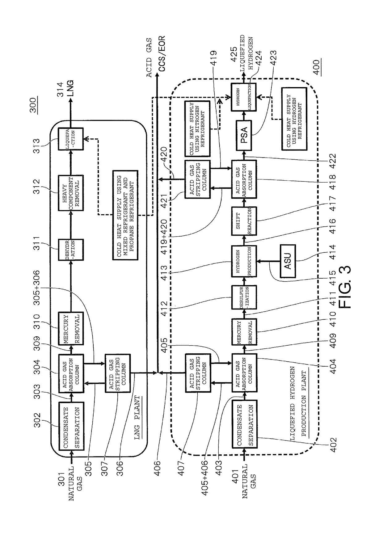
[0102]Simulation was performed taking, as Example 1, a hydrogen liquefaction process illustrated in FIG. 3 and FIG. 5 in which a refrigerant to be used for producing a liquefied natural is used for precooling in liquefaction of hydrogen.

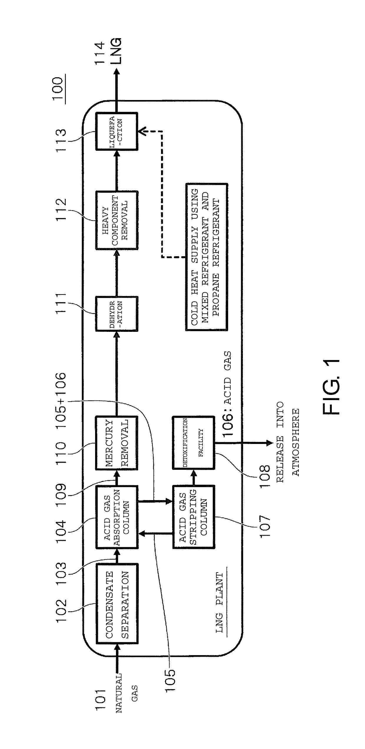
[0103]In a liquefied natural gas production plant 300, first, a condensate is separated from a natural gas 301 supplied from a gas field in a condensate separation unit 302, and thus a gas 303 containing methane as a main component is obtained. The gas contains an acid gas, such as carbon dioxide or hydrogen sulfide, and hence an acid gas 306 is absorbed and removed by a solvent 305 in an acid gas absorption column 304. The acid gas 306 having been absorbed in the acid gas absorption column 304 is stripped from the solvent 305 in a stripping column 307, and is preferably injected into the ground for carbon dioxide capture and storage (CCS) or enhanced oil recovery (EOR). Further, mercury is removed from a natural gas 309 from which the acid gas 306 h...

example 2

[0118]In Example 2, simulation was performed in the same manner as in Example 1 except that hydrogen was precooled to −158° C. using a mixed refrigerant cooled to −167° C. As compared to Example 1, a further reduction in energy consumption amount is expected through precooling of hydrogen to a lower temperature using the mixed refrigerant.

[0119]The composition of the mixed refrigerant and process parameters in Example 2 are shown in Table 3 and Table 5, respectively. In addition, power required for liquefaction of hydrogen is shown in Table 2. In Table 2, the power of the hydrogen refrigerant compressors and the power of the nitrogen refrigerant compressor are each represented by a numerical value obtained by subtracting power recovered in the expansion turbine from power required for the compressor. The power of the raw material hydrogen compressor was 23.7 MW, the power of the hydrogen refrigerant compressors was 56.7 MW, the power of the nitrogen refrigerant compressor was 12.5 M...

example 3

[0121]A process, which includes, in common, pretreatment steps for a natural gas serving as a raw material for producing a liquefied natural gas and pretreatment steps for a natural gas serving as a raw material for producing hydrogen to be supplied for production of liquefied hydrogen, is illustrated in FIG. 6 as Example 3.

[0122]As compared to FIG. 3, FIG. 6 is the same as FIG. 3 except that the condensate separation unit 402, the acid gas absorption column 404, the acid gas stripping column 407, and the mercury removal step 410 are not present in the liquefied hydrogen production plant 400. The same units, steps, and the like are denoted by the same reference numerals.

[0123]When the pretreatment steps for a natural gas are shared between a liquefied natural gas production process and a liquefied hydrogen production process, the number of units involved in condensate separation, acid gas removal, mercury removal, and the like can be reduced. As a result, a reduction in plant cost c...


PUM

PropertyMeasurementUnit
precooling temperatureaaaaaaaaaa
temperatureaaaaaaaaaa

Abstract

Provided is a production facility for liquefied hydrogen and a liquefied natural gas from a natural gas, including: a first heat exchanger configured to cool a hydrogen gas through heat exchange between the hydrogen gas and a mixed refrigerant for liquefying a natural gas containing a plurality of kinds of refrigerants selected from the group consisting of methane, ethane, propane, and nitrogen; a second heat exchanger configured to cool the mixed refrigerant through heat exchange between the mixed refrigerant and propane; and a third heat exchanger configured to cool the hydrogen gas through heat exchange between the hydrogen gas and a refrigerant containing hydrogen or helium, wherein the first heat exchanger has a precooling temperature of from −100° C. to −160° C.

Description

TECHNICAL FIELD[0001]The present invention relates to a novel production facility and production method for liquefied hydrogen and a liquefied natural gas. More specifically, the present invention relates to a novel production facility (or production method) for liquefied hydrogen combined with a production facility (or production method) for a liquefied natural gas.BACKGROUND ART[0002]It is known that both liquefied hydrogen and a liquefied natural gas (hereinafter also referred to as “LNG”) can be produced from a natural gas as a raw material.[0003]The liquefied natural gas is produced, for example, in accordance with steps illustrated in FIG. 1. Specifically, a condensate, an acid gas, mercury, a water content, a heavy component, and the like contained in the natural gas serving as a raw material are removed, and then the natural gas is cooled with a refrigerant to a liquefaction temperature to provide the liquefied natural gas.[0004]Meanwhile, the liquefied hydrogen is produced,...

Claims


Application Information

Patent Timeline
Patent Type & Authority Applications(United States)
IPC IPC(8): F25J1/00C01B3/50F25J1/02F25B9/00
CPCF25J1/001C01B3/506F25J1/0022F25J1/005F25J1/004F25J1/0052F25J1/0067F25J1/0065F25J1/0072F25J1/0087F25J1/0211F25J1/0217F25J1/0229F25J1/0236F25B9/00C01B2203/046C01B2203/048F25J2220/66F25J2270/16F25J2210/60F25J2215/10F25J2220/02F25J2220/60F25J2260/60C01B3/38C01B2203/0227C01B2203/0415C01B2203/043C01B2203/0495C01B2203/127F25J1/021F25J2260/80
Inventor WATANABE, YOSHIYUKIOMORI, HIDEFUMIMATSUHARA, TORUWATANABE, SHINTARONAKAYAMA, TORU
Owner JGC CORP
Why Eureka
Try Eureka