Method Of Determining Stress Variations Over Time In An Undersea Pipe For Transporting Fluids

a technology of stress variation and undersea pipe, which is applied in the field of pipes, can solve the problems of limited measurement and complex implementation, and achieve the effect of improving accuracy, more accurately and more rigorously performed

Active Publication Date: 2019-02-28
SAIPEM SA
View PDF0 Cites 20 Cited by
  • Summary
  • Abstract
  • Description
  • Claims
  • Application Information

AI Technical Summary

Benefits of technology

[0023]The method may also include installing at least two additional distributed optical fiber sensors along the entire length of the pipe in order to improve the accuracy with which stresses are determined

Problems solved by technology

Those calculations are generally pessimistic in order to minimize risk-taking, and for safety reasons installations are usually declared to be at risk well before they are genuinely at risk.
One of the drawbacks of that monitoring method is that measurements are limited to the positions where the Bragg grating sensors are located

Method used


Image

  • Method Of Determining Stress Variations Over Time In An Undersea Pipe For Transporting Fluids

Examples


first embodiment

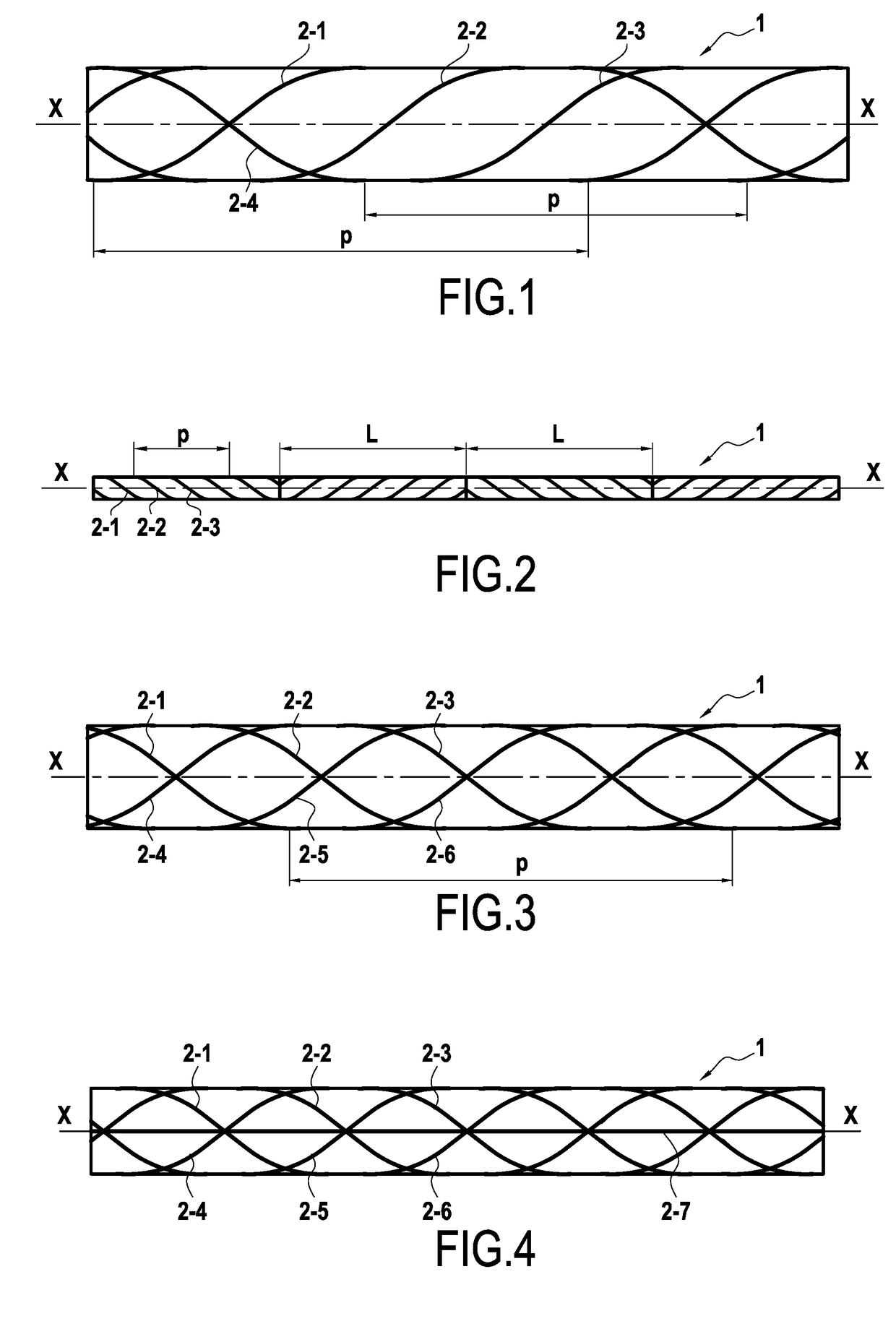
[0074]In a first embodiment shown in FIG. 1, the distributed optical fiber sensors 2-1 to 2-4 are advantageously arranged helically around the longitudinal axis X-X of the pipe 1, thereby improving their mechanical adhesion on the pipe.

[0075]In this embodiment, the optical fiber sensors 2-1 to 2-3 are positioned helically at the same pitch p, and the respective initial angular positions of those helices are offset from one another by 2 π / 3. The fourth optical fiber sensor 2-4 is positioned helically with the same pitch p but in the opposite direction to the optical fiber sensors 2-1 to 2-3, and starting from an arbitrary initial angular position.

[0076]In practice, with this helical configuration, in order to determine the stress and fatigue states of the pipe at all points of the pipe, it is necessary to know the helical positions of the optical fiber sensors 2-1 to 2-4, which positions are described by using the curvilinear abscissa given by the following equation (already mentione...

third embodiment

[0082]In a third embodiment, it is possible to measure the deformation elements u′2−r3=0 and u′3+r2=0 by adding two additional optical fiber sensors 2-5 and 2-6.

[0083]The configuration shown in FIG. 3 is an example making it possible to measure the deformation elements u′2−r3 and u′3+r2.

[0084]In this embodiment, the three optical fiber sensors 2-1 to 2-3 are positioned around the longitudinal axis X-X of the pipe in helices having the same pitch p, and with the respective initial angular positions of these helices being offset from one another by 2 π / 3. The other three optical fiber sensors 2-4 to 2-6 are likewise positioned helically with the same pitch 2 and with the same offset for their initial angular positions, however they are in the opposite direction compared with the optical fiber sensors 2-1 to 2-3.

[0085]In this embodiment, the deformation matrix A is a 6×6 matrix that is invertible, which makes it possible by means of the above-mentioned calculations to determine the str...

fourth embodiment

[0087]This fourth embodiment differs from the preceding embodiment in that the installation has an optical fiber pressure sensor 2-7 for measuring pressure inside the pipe. In this example, the pressure optical fiber sensor 2-7 is positioned in a straight line, i.e. parallel to the longitudinal axis X-X of the pipe. Thus, the optical fiber pressure sensor is insensitive to the pipe swelling under pressure and is subjected only to the elongation of the pipe under pressure. It thus makes it possible by taking the difference to obtain the pressure inside the pipe dynamically, and thus to determine the portion of the deformation that is due to internal pressure.

[0088]It should be observed that this optical fiber pressure sensor could alternatively be arranged helically around the pipe at a pitch different from the pitch of the optical fiber sensors 2-1 to 2-6.

[0089]It should also be observed that this optical fiber pressure sensor could be added to the first embodiment described with re...


PUM


Abstract

A method of determining stress variations over time in an undersea pipe for transporting fluids, the method comprising: installing along the entire length of the pipe (1) at least one distributed optical fiber sensor (2-1 to 2-4) using Rayleigh backscattering, the sensor being dedicated to measuring at least one degree of freedom of movement variation over time in the pipe at each cross section of the pipe; continuously measuring movement variation of the optical fiber sensor over time; and determining stress variations over time at each point in the pipe by time integration of the measured movement variation of the optical fiber sensor.

Description

BACKGROUND OF THE INVENTION1. Field of the Invention[0001]The present invention relates to the general field of undersea fluid transport pipes that are subjected to deformation dynamically. The invention relates more particularly to pipes for transferring hydrocarbons, e.g. oil or gas, and providing a bottom-to-surface connection or a connection between two floating supports.2. Description of the Related Art[0002]Hydrocarbon transfer pipes used for providing connections between two floating supports or for providing bottom-to-surface connections, referred to herein as “risers”, are typically made by continuously raising pipes that have previously been laid on the sea bottom, directly towards a floating support, e.g. by giving them a catenary configuration.[0003]Pipes that are raised from the bottom in this way in order to form risers need to be made out of flexible pipes when the depth of water is less than the few hundreds of meters. Nevertheless, once the depth of water reaches or...

Claims


Application Information

Patent Timeline
IPC IPC(8): G01M5/00G01K11/32G01L11/02
CPCG01M5/0091G01M5/0041G01K11/32G01L11/025G01M11/085G01D5/35361G01L1/242
Inventor SUNDERMANN, AXEL
Owner SAIPEM SA
Why Eureka
Try Eureka