Multilayer structure for hosting electronics and related method of manufacture

a multi-layer structure and electronics technology, applied in the field of electronics, can solve the problems of not always being completely isolated, not always functioning completely, and still not always being able to achieve the effect of being completely independent, establishing the required physical connection, and the layout of the connection itself may be rather complex

Active Publication Date: 2019-02-28
TACTOTEK
View PDF11 Cites 5 Cited by
  • Summary
  • Abstract
  • Description
  • Claims
  • Application Information

AI Technical Summary

Benefits of technology

[0014]An object of the present invention is to at least alleviate one or more of the above drawbacks associated with the existing solutions in the context of integral multilayer structures and electronics embedded therein.

Problems solved by technology

The used substrates may be flexible and printed materials organic, which is however, not always the case.
However, even when a multilayer structure is loaded with various electronics, it may still not always function completely in isolation, i.e. autonomously.
In some scenarios, establishing the required physical connections and the layout of connections themselves may turn out rather complex when the target components are located deep within the multilayer structure.
Yet, high level of integration resulting from embedding electronics within a multilayer structure and e.g. insulation properties of related material layers may cause concern having regard to associated thermal management as the encapsulated components could, for example, easily overheat due to reduced cooling such as convection thereof.
Still, in some scenarios the nature of the electronics to be utilized in connection with a multilayer structure, with reference to e.g. light-emitting components, may be such that they easily disturb the functioning or degrade the appearance of the overall structure and / or other embedded elements, considering e.g. light leakage in the context of the aforementioned light-emitting components.
Correspondingly, inclusion of certain electronics within a multilayer structure may prevent them from functioning in optimum or even sufficient fashion due to disturbances caused by adjacent or nearby other components or materials.
Accordingly, embedding such elements within a multilayer structure, e.g. within solid material layer, may obviously prevent the component from operating, or tedious measures have to be executed for preparing e.g. the necessary internal cavity within the structure to enable sufficient motion of the moving part(s) therein.
Further, in some applications a component such as a sensor just cannot be positioned within e.g. a closed structure to duly perform its intended function requiring interaction with the environment such as measurement of related characteristics.
Ultimately, some components may require so complex layout or generally large space or surface area that their inclusion as embedded components sandwiched between material layers is not particularly feasible in many use scenarios and contexts.
Accordingly, different impacts, rubbing, chemicals, etc. that could easily damage e.g. painted surface features do not normally reach them.

Method used


Image

  • Multilayer structure for hosting electronics and related method of manufacture
  • Multilayer structure for hosting electronics and related method of manufacture
  • Multilayer structure for hosting electronics and related method of manufacture

Examples


Embodiment Construction

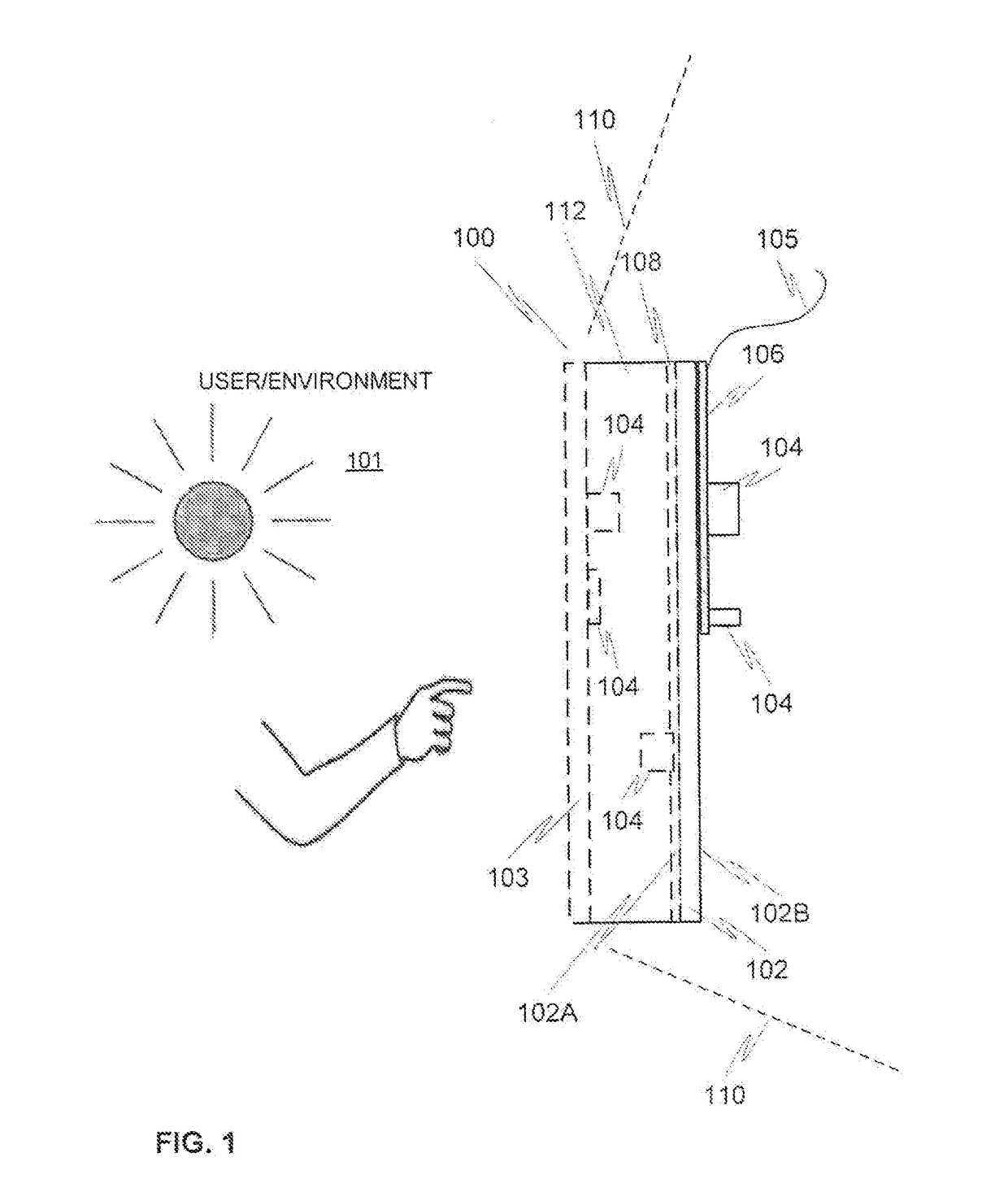
[0093]FIG. 1 illustrates, by means of a cross-sectional side view, many general concepts of various embodiments of the present invention via one, merely exemplary, realization of a multilayer structure at 100. Item 101 refers to potential use environment (outdoors, indoors, in-vehicle, etc.) and human user (if any) of the structure 100 located in the environment, whereas item 110 indicated by broken contour lines refers to a host device or host structure 110.

[0094]The finished multilayer structure 100 may indeed establish an end product of its own, e.g. electronic device, or be disposed in a host device as an aggregate part or module. It 100 may naturally comprise a number of further elements or layers not shown in the figure.

[0095]The structure 100 contains at least one substrate film 102 accommodating a number of electronic components 104 on a second side 102B thereof (which may in many, but not all, feasible use cases thus be considered as back exterior side, when the first side,...


PUM

PropertyMeasurementUnit
transmittanceaaaaaaaaaa

Abstract

A method for manufacturing a multilayer structure, includes obtaining a first substrate film for accommodating electronics, said first substrate film having a first side and an opposite second side, said first substrate film including electrically substantially insulating material, said first substrate film preferably being formable and/or thermoplastic, providing, optionally by mounting and/or by printed electronics technology, circuitry on at least said second side of the first substrate film, said circuitry being functionally connected to the first side of the first substrate film, and molding, optionally by injection molding or reactive molding, plastic material on the first side of the first substrate film so as to at least partially cover it.

Description

CROSS-REFERENCE SECTION[0001]This application is a divisional of U.S. patent application Ser. No. 15 / 687,095 filed Aug. 25, 2017, the entire disclosure of which is incorporated herein by reference.[0002]The project leading to this application has received funding from the European Union's Horizon 2020 research and innovation programme under grant agreement No 725076.FIELD OF THE INVENTION[0003]Generally the present invention relates to electronics, associated devices, structures and methods of manufacture. In particular, however not exclusively, the present invention concerns provision of an integrated multilayer structure incorporating a number of electronic components arranged on a substrate film and a molded layer provided upon the film.BACKGROUND INFORMATION[0004]Generally there exists a variety of different stacked assemblies and structures in the context of electronics and electronic products.[0005]The motivation behind the integration of electronics and related products may b...

Claims


Application Information

Patent Timeline
Patent Type & Authority Applications(United States)
IPC IPC(8): H05K1/18H05K1/02H05K3/28
CPCH05K1/0203H05K2201/10106H05K3/284H05K1/18H05K2201/0108H05K1/0274H05K3/4069H05K2201/0129H05K2201/09563H05K2201/10151H05K2203/1105H05K2203/1316H05K2203/1327H05K1/0266
Inventor KERANEN, ANTTIHAAG, RONALDHEIKKINEN, MIKKO
Owner TACTOTEK
Why Eureka
Try Eureka